4
\$\begingroup\$

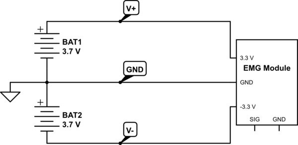
I have a circuit that uses an EMG module that requires a V+, GND and V- input. When only one of these lines are turned off, the module remains on.

schematic

simulate this circuit – Schematic created using CircuitLab

I need to be able to open and close any two lines with a single switch. I have tried to use a PNP and NPN transistor for the V+ and V- lines with little success.

Any help would be greatly appreciated.

\$\endgroup\$

3 Answers 3

8
\$\begingroup\$

I have tried to use a PNP and NPN transistor for the V+ and V- lines with little success.

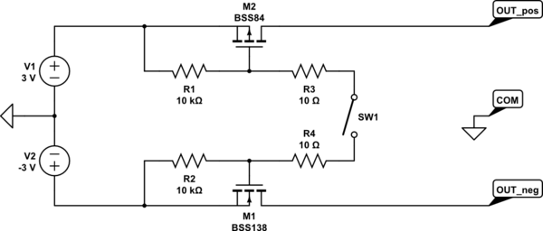
You can still use either BJTs or MOSFETs but I prefer the latter. Here's a simple circuit for you:
schematic

simulate this circuit – Schematic created using CircuitLab

When the switch is open both of the MOSFETs have their Vgs (gate-source voltage) zero. When the switch is closed the NMOS (M1) Vgs will be 3V and the PMOS (M2) Vgs will be -3V.

I put BSS138 and BSS84 as example but you can use any MOSFETs having gate-threshold voltages of less than 2 V for NMOS and higher than -2 V (e.g. -1.8 V, -1.2 V, etc) for PMOS.

One problem here is that there's no guarantee of turning on or off both of the MOSFETs right at the same time. The difference can be in nanoseconds or seconds or microseconds. I'm not sure if this is going to be a problem for your application.
\$\endgroup\$
3
  • \$\begingroup\$ Yours works easily with bipolar transistors. Mine would be more fiddly. Mine allows higher Vgsth FETS - yours about 2 - 3 volts. Mine about double. I use one extra transistor. You none. || Consider a design where one main switch is the physical switch :-) \$\endgroup\$
    – Russell McMahon
    Commented Jan 9 at 12:51
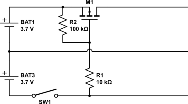
  • \$\begingroup\$ One FET. 1 or 2 resistors :-). FET in eg low rail is turned on by a gate resistor to the high side load rail. A suitable FET would need NO gate resistor :-). \$\endgroup\$
    – Russell McMahon
    Commented Jan 9 at 12:54
  • \$\begingroup\$ Any comment on my single FET idea in my answer)? Off time of FET leg is a few time constants of R2 + the gate capacitance. \$\endgroup\$
    – Russell McMahon
    Commented Jan 10 at 2:34
7
\$\begingroup\$

I would use a Double Pole Single Throw (DPST) switch - "Double Pole" means that the switch will switch two separate circuits simultaneously.

\$\endgroup\$
1
  • \$\begingroup\$ +1 for simplicity! (timing problem put aside) \$\endgroup\$
    – Ek1noX
    Commented Jan 10 at 10:07
2
\$\begingroup\$

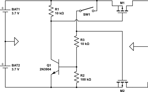
This "should" work.

Using FETs allows high resistance switching.

Switch off.
Q1 off. M1 gate high so off.
M2 gate low so off.

Switch on.
Q1 on.

M1gate low so on.
M2 gate high so on.

This could be done with bipolar transistor switches.
That may take one or maybe 2 more transistors.

schematic

simulate this circuit – Schematic created using CircuitLab


Albert Einstein is reported to have said "Things should be made as simple as possible, but not simpler". This is rather pushing Albert's limits :-).

schematic

\$\endgroup\$
0

Your Answer

By clicking “Post Your Answer”, you agree to our terms of service and acknowledge you have read our privacy policy.

Not the answer you're looking for? Browse other questions tagged or ask your own question.