3
\$\begingroup\$

I am working on a PCB board that incorporates three LM1085IT voltage regulators, all connected to a common 12 V input source. The intended configuration is to obtain a regulated 5 V output from each LM1085IT. However, I am encountering an issue where one LM1085IT is providing the expected 5 V output, while the other two are outputting 12 V, despite having identical configurations.

Here are the details of the setup:

  • Input voltage: 12 V
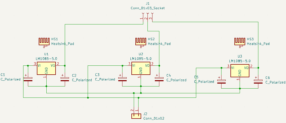
  • Three LM1085IT voltage regulators in parallel
  • All LM1085IT components are configured for a 5 V output
  • No load or minimal load conditions on the regulators

Is this discrepancy in output voltage likely to be a result of faulty components, or could there be other factors contributing to this issue? I have double-checked the connections and configurations, and they seem consistent across all three LM1085IT components. Any insights or troubleshooting tips would be greatly appreciated.

Schematic

EDIT: I rearranged the placement of the operational regulator, exchanging it with one of the faulty regulators. Currently, it appears that the previously functional regulator is no longer regulating properly, delivering 12V, while the other one is providing 5V. This suggests that the issue likely resides within the circuit. Any suggestions on what could be causing this problem?

EDIT-2: I reprinted the PCB, and initially, every regulator exhibited a 5V output. However, after several instances of use, the second regulator resumed outputting 12V.

EDIT-3: After successfully reassembling the circuit board, all regulators were initially functioning correctly. However, following several applications, the middle regulator inexplicably began generating a 12V output. Unfortunately, this issue went unnoticed until the connected device experienced damage from overvoltage. Subsequently, the load on the device increased beyond the minimum threshold. Even after the device was destroyed, the middle regulator consistently produces a 12V output under varying loads.

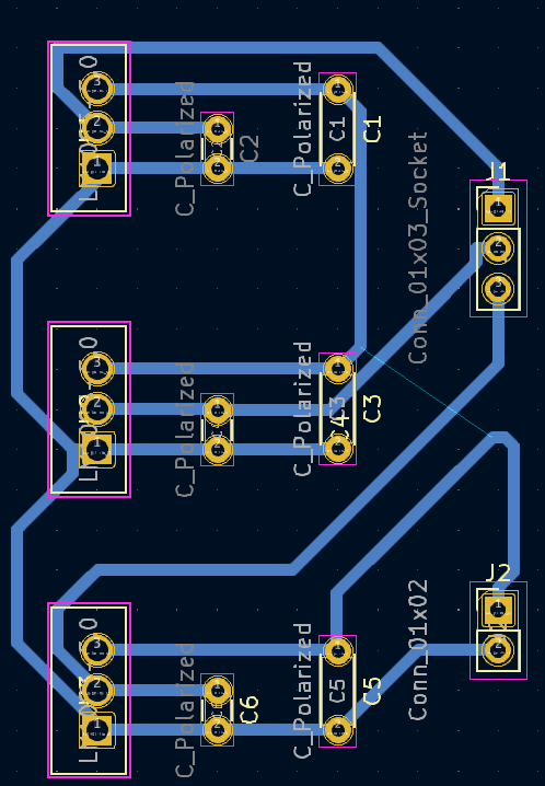
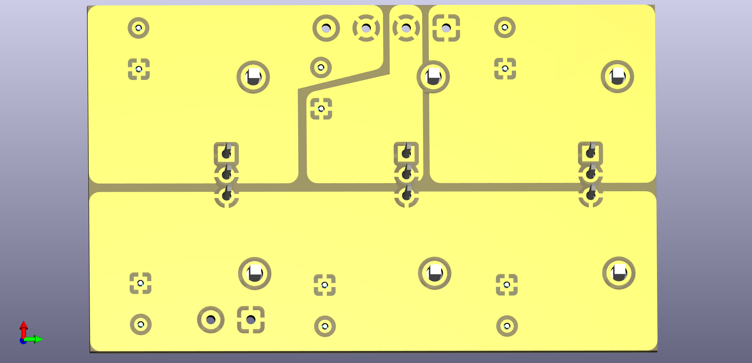
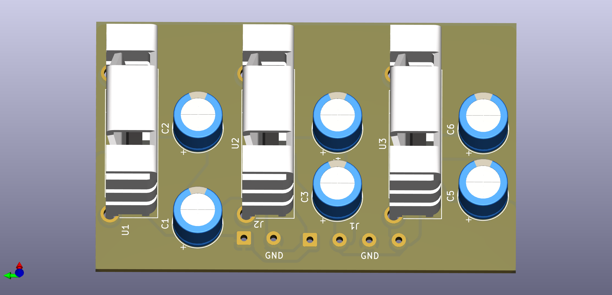
Layout

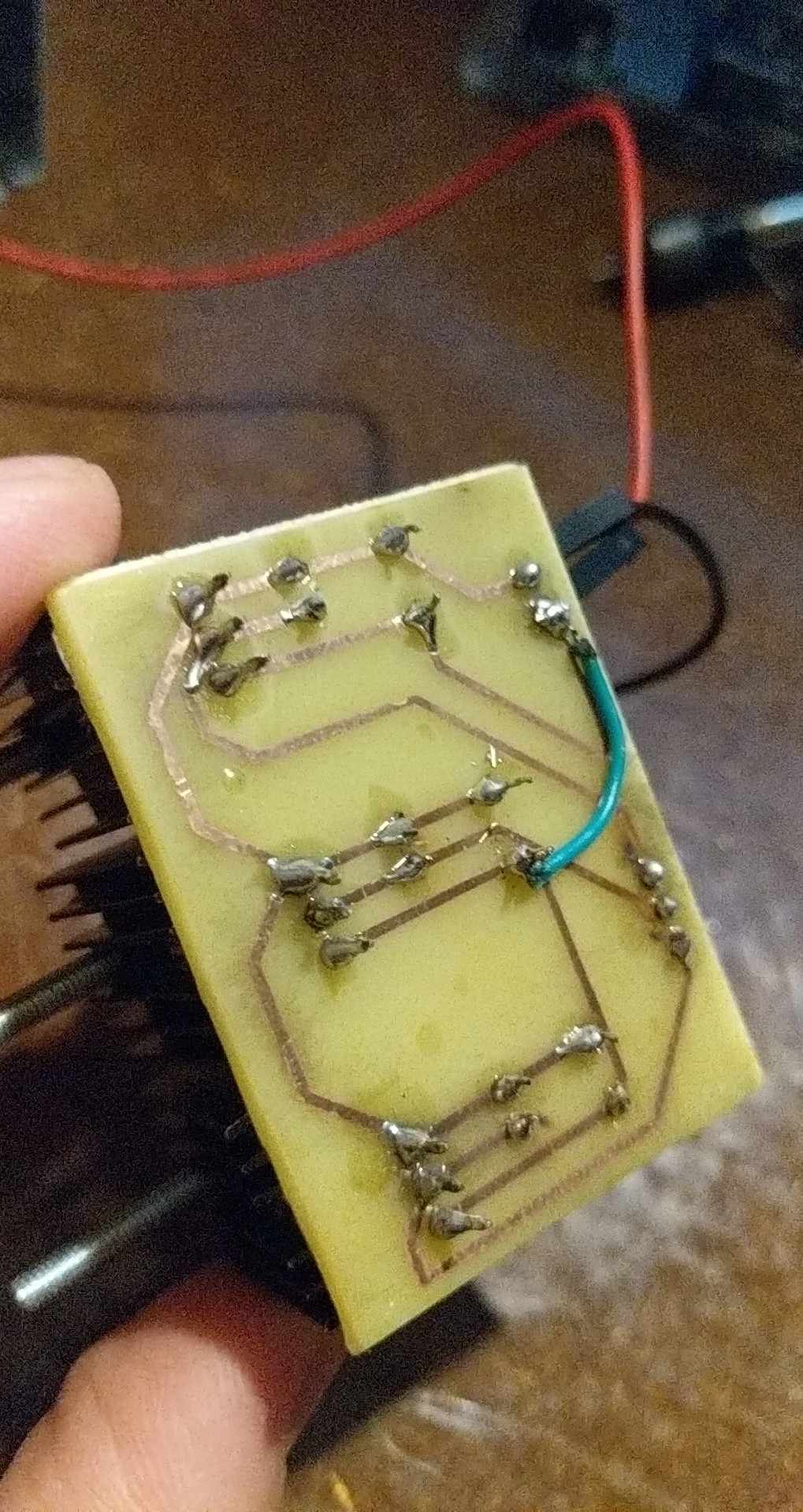
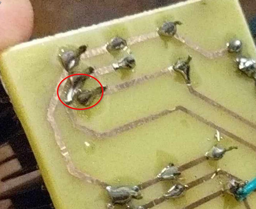
Soldered board

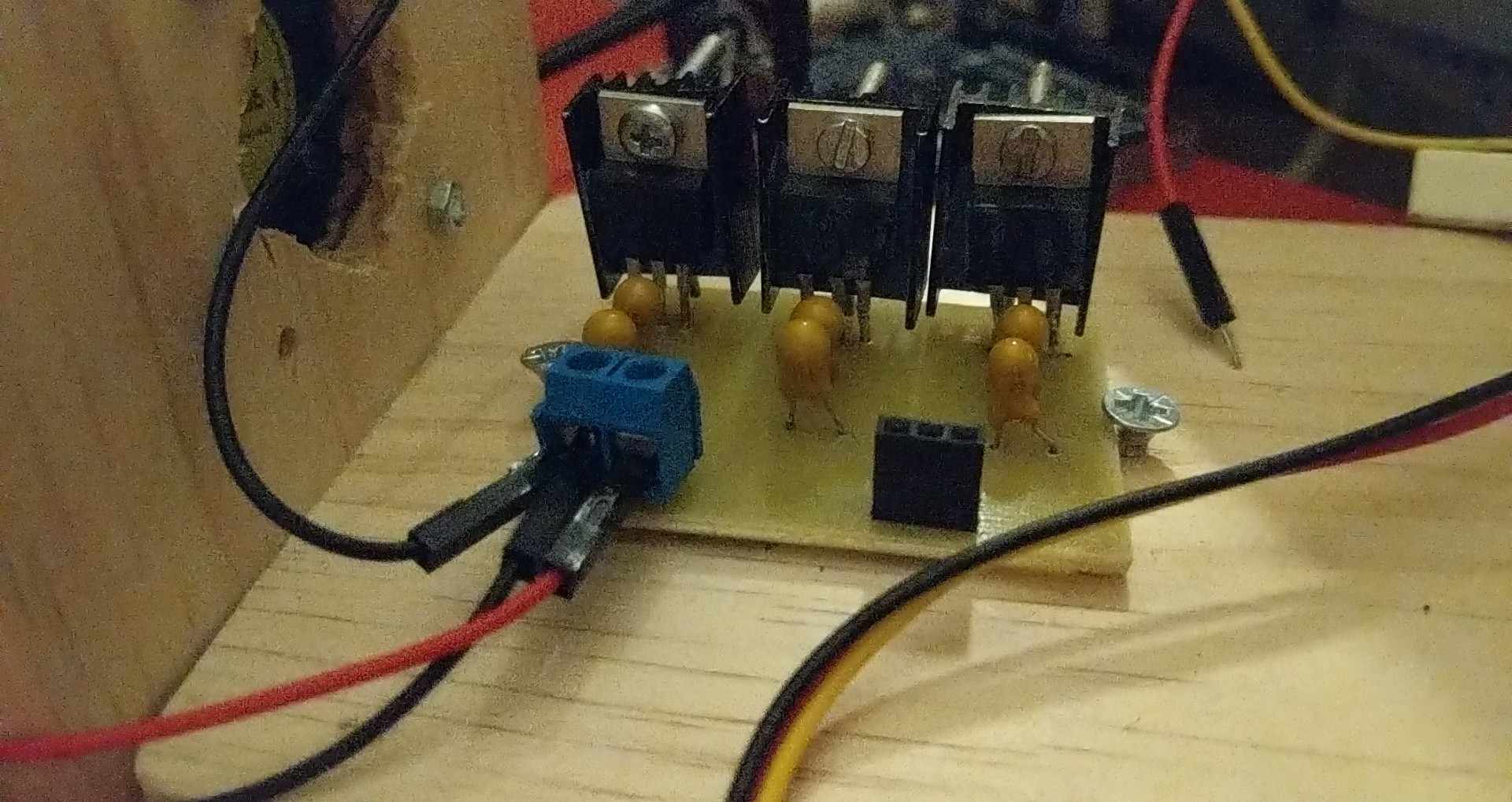
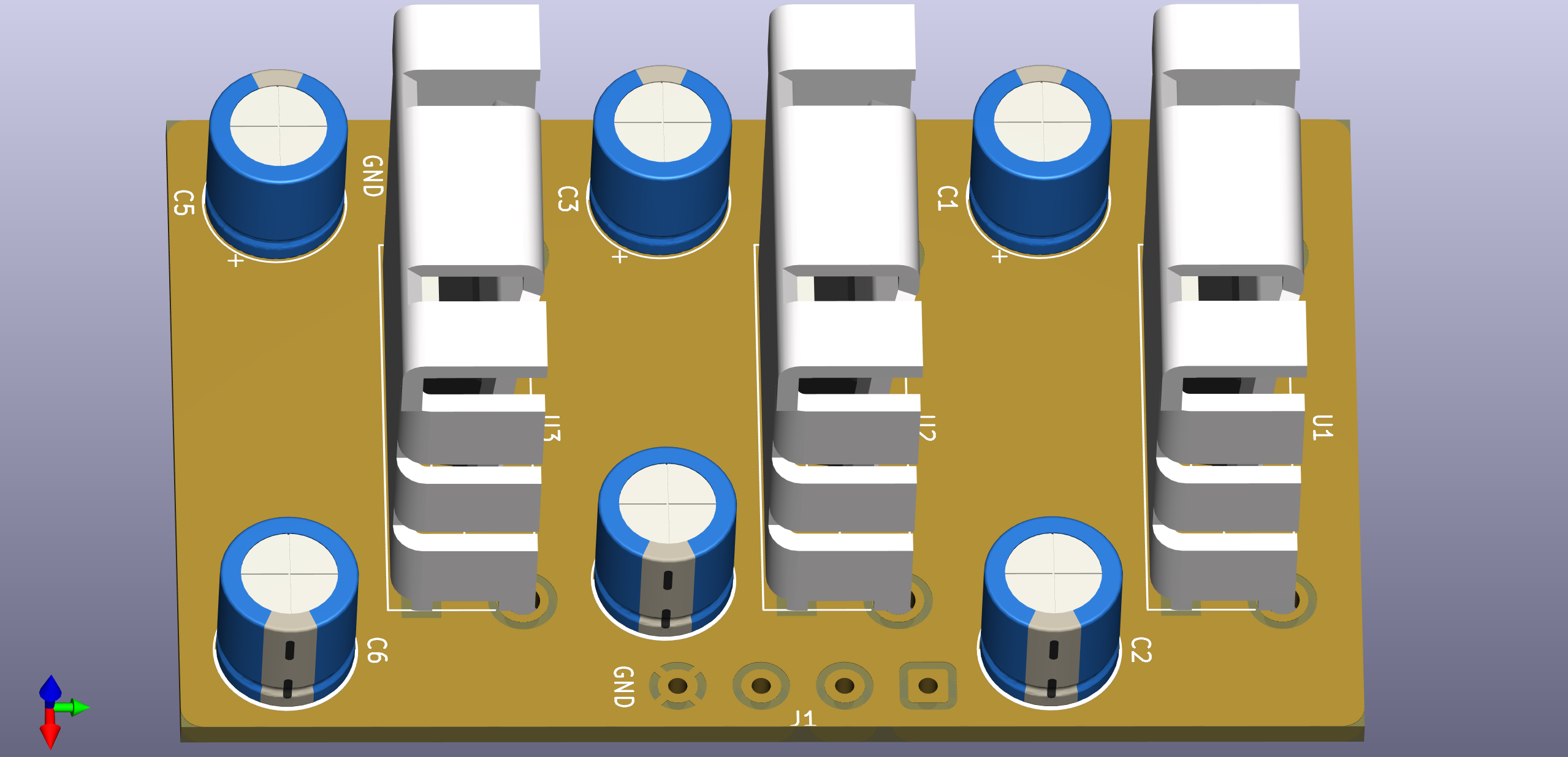
Top View

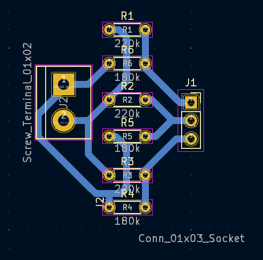
EDIT-4: Given that my input voltage remains stable at 12V, and aiming for an output voltage around 5V (with a tolerance range of 4.8V to 6.3V), I considered implementing three voltage dividers using resistor values of R1 = 220k and R2 = 180k. However, upon measuring the output voltage, I observed that the middle divider exhibited the same problem as the middle regulator, both outputting 12V (equivalent to the input voltage), while the other dividers yielded the correct 5V. While this alignment may be coincidental, it could provide valuable insights into the underlying issue with the regulators.

Voltage Divider

\$\endgroup\$
8
  • 1
    \$\begingroup\$ A picture of your layout and the board as soldered together might help spot problems. \$\endgroup\$ Commented Jan 29 at 18:06
  • \$\begingroup\$ For the next board revision, you could double the trace width, where space permits, increase the size of the solder pads, and avoid those 45° traces that bring adjacent traces ~40% closer than they need to be. It should then be more forgiving of places that get etched too much, and easier to solder to. IMHO. \$\endgroup\$ Commented Jan 31 at 15:58
  • \$\begingroup\$ What's the other side like? The metal tabs of the regulators are connected to the Vout pin, so if the heatsinks are touching something else this could explain things. \$\endgroup\$ Commented Jan 31 at 19:23
  • 1
    \$\begingroup\$ All I can say is that I've put your exact circuit together (not sure if the capacitors are the same), loaded it up, and it works fine. Perhaps the parts you got are fake. The ones I've got are 20 years old and were still manufactured by National Semiconductor before they got acquired by TI. The layout is rather marginal for, presumably, a high power linear regulator circuit. But that's not the immediate source of trouble - that'll only happen once you fully load the output. \$\endgroup\$ Commented Jan 31 at 19:52
  • \$\begingroup\$ Each regulator powers a MG996R servo motor. Could that have caused the regulators to break? \$\endgroup\$ Commented Feb 1 at 15:38

4 Answers 4

4
\$\begingroup\$

Sure looks like a short from input to output here, but it could be reflections from the flux residue. Clean the board properly and put a strong light behind it to confirm.

enter image description here

\$\endgroup\$
6
  • \$\begingroup\$ Yes the soldering is a bit dodgy, wanted to post that as well. Using a multimeter could also help, there should be no direct connection between input and output. \$\endgroup\$
    – Arsenal
    Commented Jan 31 at 15:56
  • \$\begingroup\$ I used the multimeter in the buzzing mode, I got no buzz and no value on the screen, there is no short. Moreover this regulator is the one that was always outputting 5V. \$\endgroup\$ Commented Jan 31 at 16:04
  • 1
    \$\begingroup\$ If you have a short from output to input you'll get exactly the input voltage at the output. If you have an open on pin 1 you'll get a bit less most likely. Either of those problems, which could either be due to either bad PCB etching or soldering can cause the problems as described. \$\endgroup\$ Commented Jan 31 at 17:20
  • \$\begingroup\$ Wouldn't the buzzer of the multimeter make a noise if there was a short? The etching was done using 16% HCl and 3.1% H2O2. \$\endgroup\$ Commented Jan 31 at 20:53
  • 2
    \$\begingroup\$ @KarampistisDimitrios sometimes you think the tip of the probe is making contact, but it's actually not, especially if there's a lot of dirt or flux. But with your simple PCB you should be able to visually confirm a gap between every trace, and even scratch the board with a blade in-between pads to remove any ambiguous material. \$\endgroup\$ Commented Jan 31 at 21:04
2
\$\begingroup\$

No load or minimal load conditions on the regulators

This is from the datasheet:

enter image description here

Try putting a 500 Ω resistor on the output and see if it starts regulating again.

\$\endgroup\$
6
  • 1
    \$\begingroup\$ Isn't minimum load current specified only for the ADJ version, and not for the fixed 5 V version? Still, worth the try. \$\endgroup\$
    – ocrdu
    Commented Jan 24 at 2:35
  • \$\begingroup\$ @ocrdu It says the test condition was with the ADJ version, but the only difference between them is that the ADJ version lacks the internal voltage divider, so I don't think they're implying that the minimum output current requirements are specific to that device. My reading is that the device must have a load (which is very common on linear regulators). I think they tested on the ADJ version since it can have the largest voltage drop. \$\endgroup\$ Commented Jan 24 at 3:12
  • \$\begingroup\$ The LM1085IT-5.0 version I'm using doesn't have an adjustable output. However I gave this solution a go. I connected an 1kΩ resistor to the output of the LM1085IT-5.0 and the GND and the voltage was close to 12V. The first regulator's output is 5V even without load. I also triple checked and the are no shorts on the pcb. \$\endgroup\$ Commented Jan 24 at 11:49
  • \$\begingroup\$ Sounds like you have open grounds where the "faulty" regulators are stuffed. \$\endgroup\$
    – MOSFET
    Commented Jan 29 at 15:47
  • \$\begingroup\$ If the regulator in one position of the board works, and the same regulator in another position does not, there must be some fault on the board at the non-working positions. \$\endgroup\$ Commented Jan 29 at 17:11
1
\$\begingroup\$

If I was doing the layout, I'd use large copper pours, and put the capacitors not too close to the heatsinks, if possible.

Both input and output connectors need grounds, so the output should be 4 pads/pins, not only 3.

I've put it quickly together in KiCad:

enter image description here enter image description here

The heatsinks are Fischer FK224 clip-on type, since I've got them laying around in the lab.

The "connectors" are for wires soldered directly into the board. I suggest either doing that, or using screwed terminal blocks (Phoenix-style). There are versions that are plug-able: screw the wires into the plug, then plug the plug into the board-side receptacle.

Note a few things:

  1. I'm using thermal relief connections on the copper fills.
  2. The top layers has the ground plane only.
  3. The bottom layer has the input and output planes.
  4. There are top layer cut-outs under the bosses ("short legs") protruding from the bottom of the heatsink.

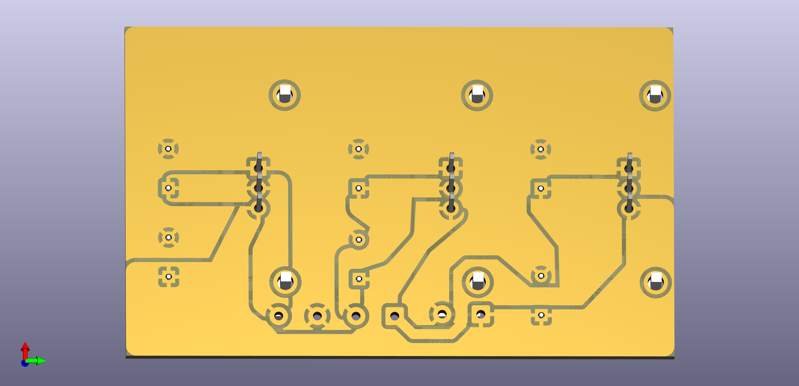
If I was limited to single-sided layout, I'd do it as follows:

enter image description here enter image description here

The connectors had to be moved to one side, with a slightly different pinout, to make the layout possible without jumpers.

\$\endgroup\$
5
  • \$\begingroup\$ One of my major problems is that I can't use a double sided copper board. When dealing with the output ground (GND), given its common nature, I promptly derive it from the source. Instead of directly soldering the wires onto the board, I opt for using sockets for the connectors on the printed board. I am struggling to comprehend how my layout results in the regulator outputting 12V instead of 5V. Could you provide more clarity on this particular aspect? \$\endgroup\$ Commented Jan 31 at 23:01
  • \$\begingroup\$ @KarampistisDimitrios I'm not sure what you're doing wrong. Basic troubleshooting: try one regulator at a time, separately on a breadboard, without soldering to the very fragile board you have. There's also a single-layer layout I've shown. It's not perfect but can be a starting point to give you an idea of what's needed. \$\endgroup\$ Commented Jan 31 at 23:54
  • \$\begingroup\$ @KarampistisDimitrios Also: the Heatsink_Pad component is for heatsinks that have connections to the PCB. On the regulators you have, the heatsink is connected to the output voltage, not ground (!). \$\endgroup\$ Commented Jan 31 at 23:57
  • \$\begingroup\$ The heatsinks are connected to nowhere. \$\endgroup\$ Commented Feb 1 at 7:44
  • \$\begingroup\$ @KarampistisDimitrios And of course they are not connected, but just in case they were, it's not ground :) \$\endgroup\$ Commented Feb 5 at 13:19
0
\$\begingroup\$

I would like to express my gratitude to all those who responded to my inquiry. Ultimately, I opted for a voltage divider given the stable 12V DC power source. Initially, the central component of the divider circuit was malfunctioning, but after fabricating a new PCB, everything functioned seamlessly. Regarding the regulators, I am uncertain about the issue. While the dividers were procured from a reputable source, there is a possibility that they were defective from the outset.

\$\endgroup\$

Your Answer

By clicking “Post Your Answer”, you agree to our terms of service and acknowledge you have read our privacy policy.

Not the answer you're looking for? Browse other questions tagged or ask your own question.