1
\$\begingroup\$

This answer gives a good explanation of how to use a keypad matrix to minimize GPIO usage by scanning rows and columns to find a button press when an interrupt triggers. This scales very nicely for large arrays of buttons---but what about when the button count is small? For example, a 4-button matrix still requires 4 GPIOs (2x2), so you might as well wire each button to its own GPIO.

In our case, we would like to wire up a 5-button (up/down/left/right/ok) keypad.

Question:

  • What is the minimum number of GPIOs that are required to wire up 5 push-buttons, and what would the circuit look like?
    • Ideally without an add-on chip, but see below.
    • Detecting simultaneous button presses is not necessary.

(A clever circuit without an addon-chip is preferred, as we are trying to minimize BOM cost. However, some kind of multiplexer chip shift-latch-thing or whatever would be acceptable as part of an answer if it's inexpensive (<$0.50 in qty >=100). I would like to avoid more expensive (but otherwise perfect) i2c scanning chips like this one, but I'm open to an i2c solution if the cost is low.)

FYI: We're using an ESP32-C6.

\$\endgroup\$
4
  • 2
    \$\begingroup\$ Do you have an A/D input available? \$\endgroup\$
    – vir
    Commented Jan 30 at 22:15
  • \$\begingroup\$ @vir, yes. Its an ESP32-C6 with a 12-bit SAR ADC (not sure what SAR means). \$\endgroup\$
    – KJ7LNW
    Commented Jan 30 at 23:35
  • \$\begingroup\$ Switches or pushbuttons? Switches could be DPDT but pushbuttons only SPST with NO output. \$\endgroup\$
    – Justme
    Commented Jan 31 at 6:56
  • \$\begingroup\$ @Justme, good point. updated post. \$\endgroup\$
    – KJ7LNW
    Commented Feb 1 at 20:51

4 Answers 4

4
\$\begingroup\$

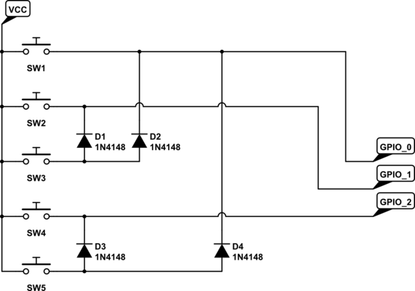
You can do this with 3 GPIO's provided only one unique keypress at a time using diode logic.

schematic

simulate this circuit – Schematic created using CircuitLab

Switch data is encoded in BCD. You may be able to get 4 rectifiers in a single package for under a buck. Check my math before building this.

\$\endgroup\$
5
  • \$\begingroup\$ Neat! Generically speaking, what is this circuit called? \$\endgroup\$
    – KJ7LNW
    Commented Jan 30 at 23:52
  • \$\begingroup\$ Not sure exactly. Something along the lines of "diode matrix encoder"? \$\endgroup\$
    – MOSFET
    Commented Jan 30 at 23:54
  • \$\begingroup\$ For others who might find this, here is a video with an example. \$\endgroup\$
    – KJ7LNW
    Commented Jan 31 at 1:32
  • \$\begingroup\$ You need three pull-down resistors to assure low input states. \$\endgroup\$
    – AnalogKid
    Commented Feb 2 at 13:59
  • \$\begingroup\$ @AnalogKid They are already included in the MCU. \$\endgroup\$
    – MOSFET
    Commented Feb 2 at 14:10
3
\$\begingroup\$

If you are scanning a multiplexed display you often can share most or all of the lines with switches.

If you have an ADC you could put different resistors in series with each switch (one could be 0Ω) and detect the voltage across another resistor.

If you need to detect (and distinguish) multiple switches closed at once, you'll need a more complex circuit, for example the 2x2 muxed circuit would have to have a diode for each switch. It's possible the resistor idea could be made to work reliably just with accurate resistors.

In the above cases, it could be zero GPIOs or 1 (ADC input) GPIO.

\$\endgroup\$
2
\$\begingroup\$

If the GPIO pin can be configured as the input to an internal A/D converter, then you need only 1 pin plus 5 resistors.

All five resistors connect to the input pin. 1 resistor goes to Vcc. Each of the other 4 resistors goes to a switch. Those 4 resistors all have different values, so each of them forms a different ratio voltage divider when grounded through a switch.

If Vcc = 5 V and the pull-up resistor is 20 K then here is one possible resistor set and the created output voltages:

5 K >> 1 V

13.3 K >> 2 V

30 K >> 3 V

80K >> 4 V

Update: The above method is a simple way to go if all of the switches have one terminal in common, such as all five switches having one terminal connected to GND or Vcc.

There is another configuration where all resistors are in series, and the switches connect different taps to the A/D input. It still takes five resistors, but they can be equal-valued. For this method, both switch terminals must be available.

\$\endgroup\$
4
  • \$\begingroup\$ could this scheme handle multiple keys pressed at once? \$\endgroup\$
    – Pete W
    Commented Jan 31 at 0:59
  • 1
    \$\begingroup\$ @PeteW, yes, if you use a binary resistor R-2R ladder and stay within the resolution of your ADC, +/- noise. If you have a 12-bit ADC, then you might get 10 or 11 bits of usable multi-key resolution. Somehow you have to add the output voltages with an op-amp or something. \$\endgroup\$
    – KJ7LNW
    Commented Jan 31 at 1:25
  • \$\begingroup\$ @PeteW, here is another video showing the opamp. \$\endgroup\$
    – KJ7LNW
    Commented Jan 31 at 1:30
  • \$\begingroup\$ That's a lot of parts and complexity for something as simple as 4 buttons. Also, in your question you state that you do not want to add another chip to the design. \$\endgroup\$
    – AnalogKid
    Commented Jan 31 at 14:36
2
\$\begingroup\$

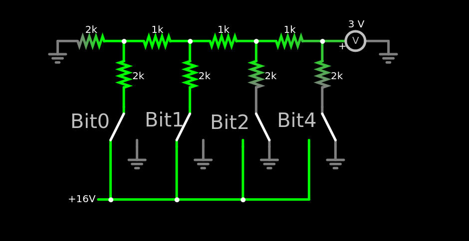
Use an ADC with an R-2R ladder, which is also known as a "121 circuit". Click here for the simulation (and live-toggle the switches); the schematic is below.

Add more bits as you see fit. With a 16V input and bit 0 and 1 are on, so 3V output. If your ADC is "ideal" then its binary measurement using its analog Vref (instead of 16V in this example) will equal the bits that are on. In reality there will be noise, so adjust as necessary. Maybe shift off the lower "noise" bits.

4-bit ADC

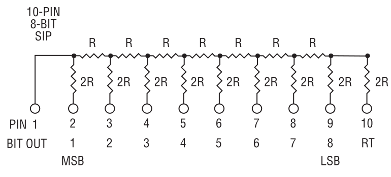
FYI, these are called "R/2R" ladders and parts like the Bournes 4610X-R2R-103LF can be found at your favorite distributor. This is what the datasheet shows for the R2R version (which is an exact mirror of the "121" schematic above):

Bournes R2R Ladder

Just ground pin 10, measure pin 1, and switch the other pins on-and-off for your bits. Important: the "off" state must pull hard to ground or your analog measurement will be wrong...so SPDT's or some other mechanism is required.

Bournes R2R SIP

\$\endgroup\$
5
  • \$\begingroup\$ Why this ladder? As you have essentially 5 buttons, not 5 switches to set e.g. pins as digital 1 and 0, but buttons can only leave open or connect. It would be just simpler with 5 buttons, 5 resistors, and the ADC input. \$\endgroup\$
    – Justme
    Commented Jan 31 at 6:59
  • \$\begingroup\$ An R-2R ladder requires SPDT switches, but the TS described only SPST switches. There is a way around this, but it requires even more resistors. Nothing is going to take fewer parts and connections than a simple resistor string. \$\endgroup\$
    – AnalogKid
    Commented Jan 31 at 14:07
  • 1
    \$\begingroup\$ I'm confused - are you answering your own question? \$\endgroup\$
    – AnalogKid
    Commented Jan 31 at 14:07
  • \$\begingroup\$ @AnalogKid, ya...but only as a reference to others. I like MOSFET's answer best because it only adds 2x BAT54A's or BAW56's. \$\endgroup\$
    – KJ7LNW
    Commented Feb 1 at 20:50
  • \$\begingroup\$ @AnalogKid, I just realized my previous comment is contradictory: resistors are cheaper than diodes...but I like the raw digital approach, no ADC fuzz in the measurement and it scales to 7 buttons. We may still go to an analog version like your answer below if we need to free more GPIO pins. Note that this answer wasn't meant to replace yours, but rather, it's an answer to PeteW's comment about detecting simultaneous button presses with series resistors and an ADC. \$\endgroup\$
    – KJ7LNW
    Commented Feb 1 at 21:07

Your Answer

By clicking “Post Your Answer”, you agree to our terms of service and acknowledge you have read our privacy policy.

Not the answer you're looking for? Browse other questions tagged or ask your own question.