I am working on a circuit that will use the ADC on an Arduino (Adafruit Feather M4 Express) to measure a small signal, so I want a minimum of noise. Testing the Arduino on a breadboard with a DC test analog signal, and configuring it in oversampling mode to get 15 bit resolution, I see drift over a range of 6 counts in 32767 (0.18%) in a one second monitoring period, which is acceptable for the application.
When I also wire up a Newhaven 2x16 char OLED module, the ADC drift increases 10x, to 60-70 counts - not OK.
The Arduino pulls about 15 mA. The OLED module adds 25 mA load on the 5 V bus. When I probe the 5V bus I see a 100 mVpp noise signal at 228 kHz with the OLED plugged in, silence otherwise.
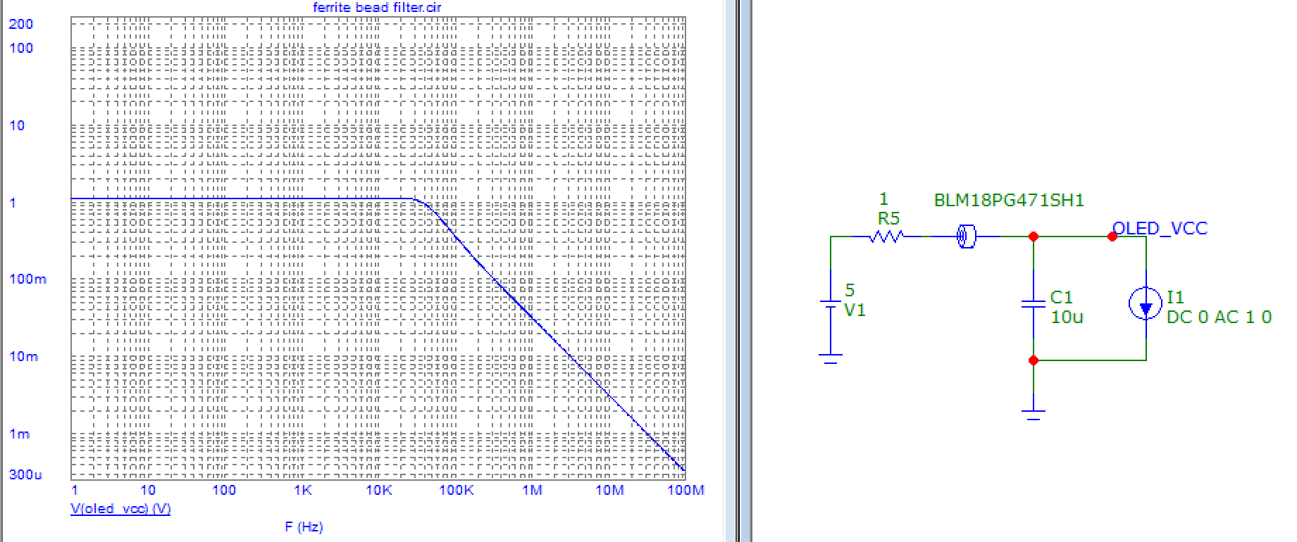
A 4R7 in series with the OLED power wire (it's connected via a set of 12" 28 AWG wires to the pin header; in the final application it will be panel mounted so this is a realistic test) does knock the spikes down a bunch, though it's also dimmer due to the 100 mV drop. A 100 uF electrolytic helps even more - but this would occupy board space that's in short supply near where I'll connect the OLED wiring harness to the board so I'd prefer to avoid it if I can. (An LRC filter makes it whisper quiet but uses up even more space and voltage headroom I don't have.)
The weird part however is that the OLED module drags down the voltage beyond what I can account for. If not plugged in, I measure 4.95 V on the breadboard rail. With the Vcc wire for the module plugged into the rail it drops to 4.75 V! The PSU is a Siglent linear supply. It is not in current limit, it's sourcing only 50mA and the cutoff is configured to 10x higher. With the OLED power passing thru the resistor the 5v bus is somewhere in between these voltage extremes, but wanders around unstable.
This leaves me confused and also doubting the utility of the filter tests. Is the issue just that breadboards suck? 28 AWG jumpers too thin? (I don't have any thicker DuPont header jumpers on hand to test with.) The PSU is connected to the breadboard through appropriately thick gauge cables.
In the application I plan to use a 4 layer board with a 5 V power plane, and a wiring harness with 24 AWG leads for the display. Should I just ignore all this as breadboard jankiness and trust it'll work out on the PCB? Or do I need a filter - or something even more drastic to combat this inexplicable supply undervoltage?
I plan to set a 0R jumper on the board near the pin for the Vcc lead that I can replace with 4R7 if needed, I've got space for that at least. The analog and digital domains on the board are also well separated with a solid inner ground plane.

