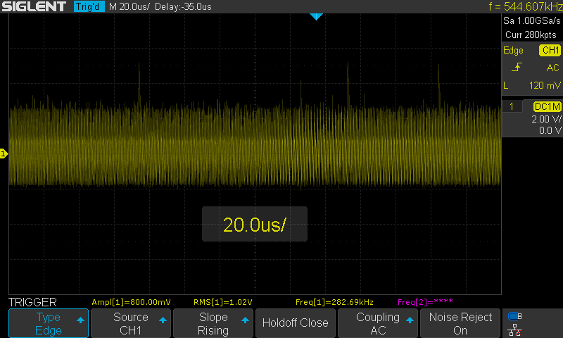
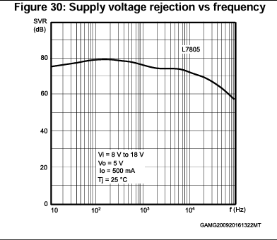
You seem to be using switch mode wall warts as power supplies.
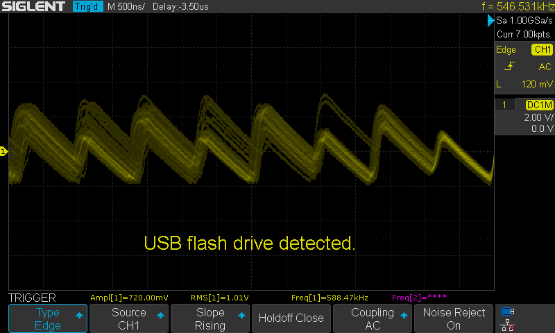
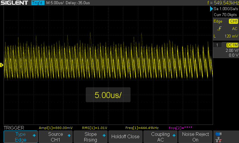
These output a lot of electrical noise, both differential mode and common mode.
One solution is to buy anothet set of wall warts that are not switch mode power supplies. Another solution is to make your PCB to be more complex and expensive to filter or smooth away the noise.
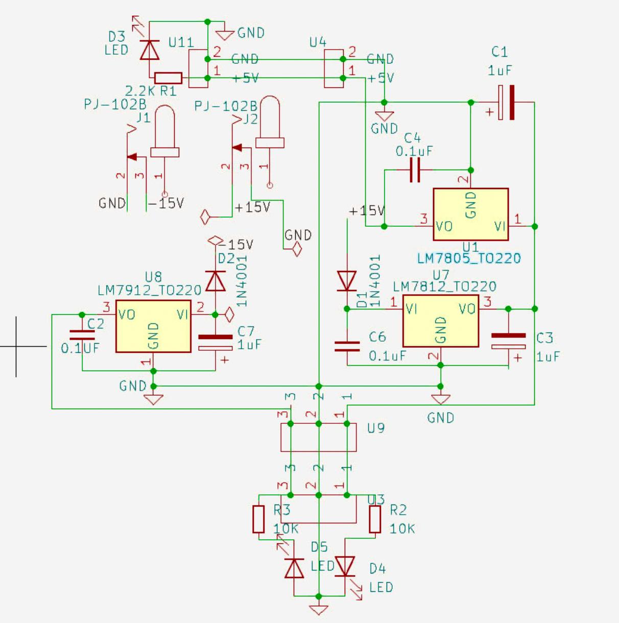
For this purpose, the regulator input capacitors are too small. You need few tens if not a few hundred microfarads, preferably after a resistor or inductor to have an RC or LC filter to remove noise.
As electrolytic caps are quite poor at high frequencies, having one larger electrolytic and one 100nF ceramic for filtering high frequencies would be much better. Unless you buy polymer electrolytics.
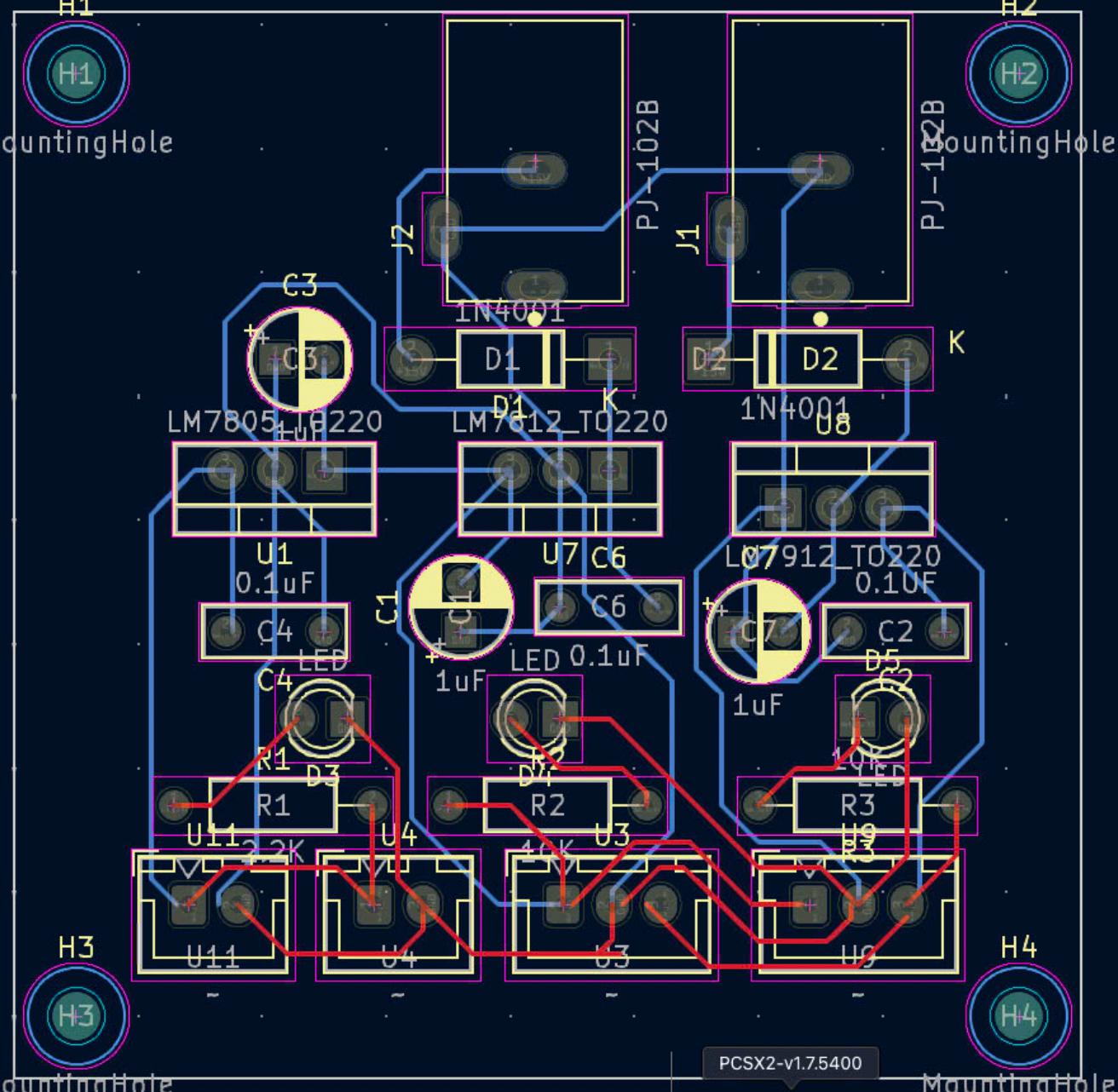
The PCB wiring is also quite narrow, wider tracks would pass more current with less voltage drop. It could be a lot better. It's two-sided, with both sides mostly etched empty from copper that could have been used to make a proper ground plane and wide tracks to easily carry a lot of current.
