1
\$\begingroup\$

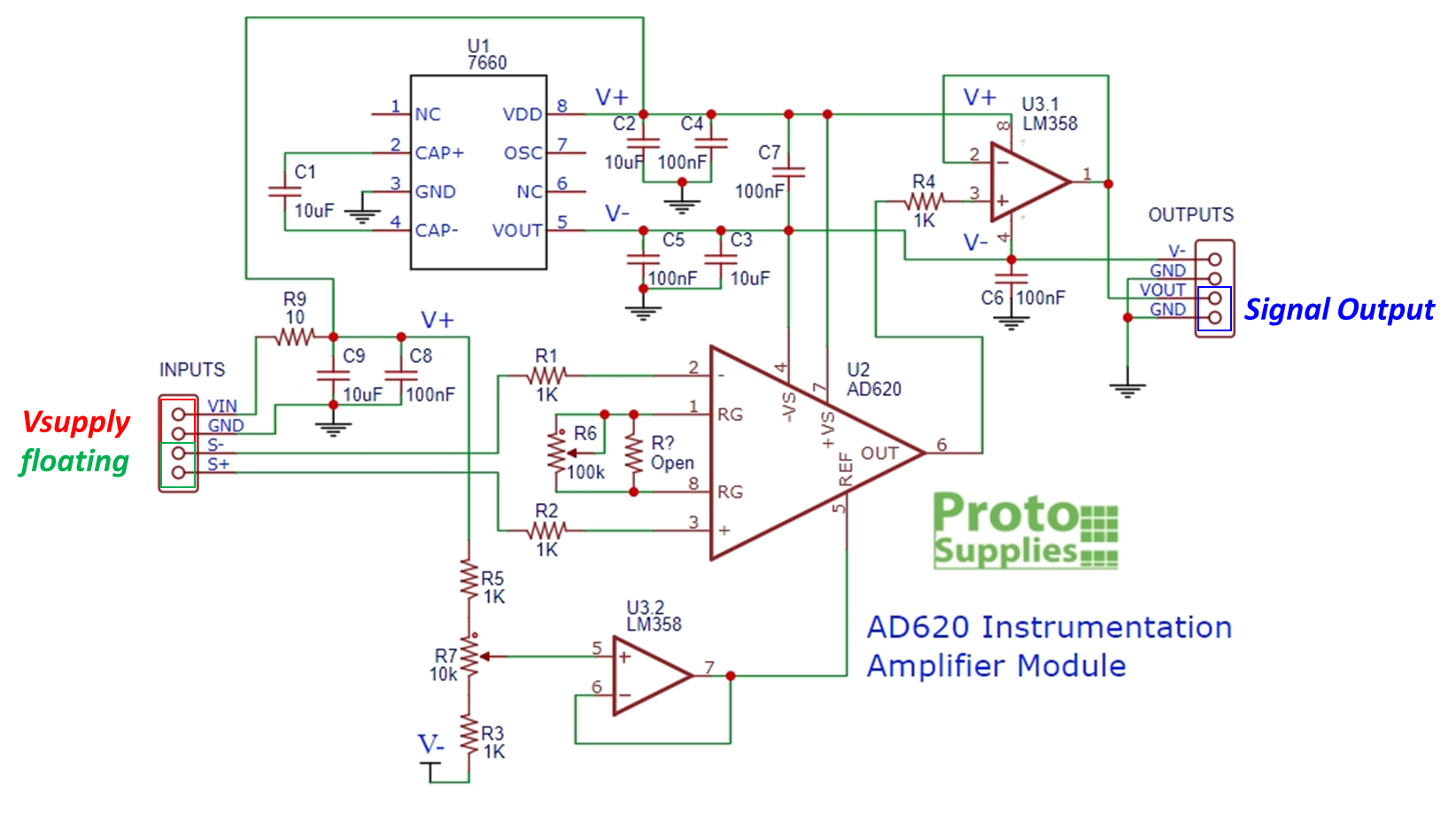
I bought an AD620 instrumentation amplifier module and below is the module schematic.
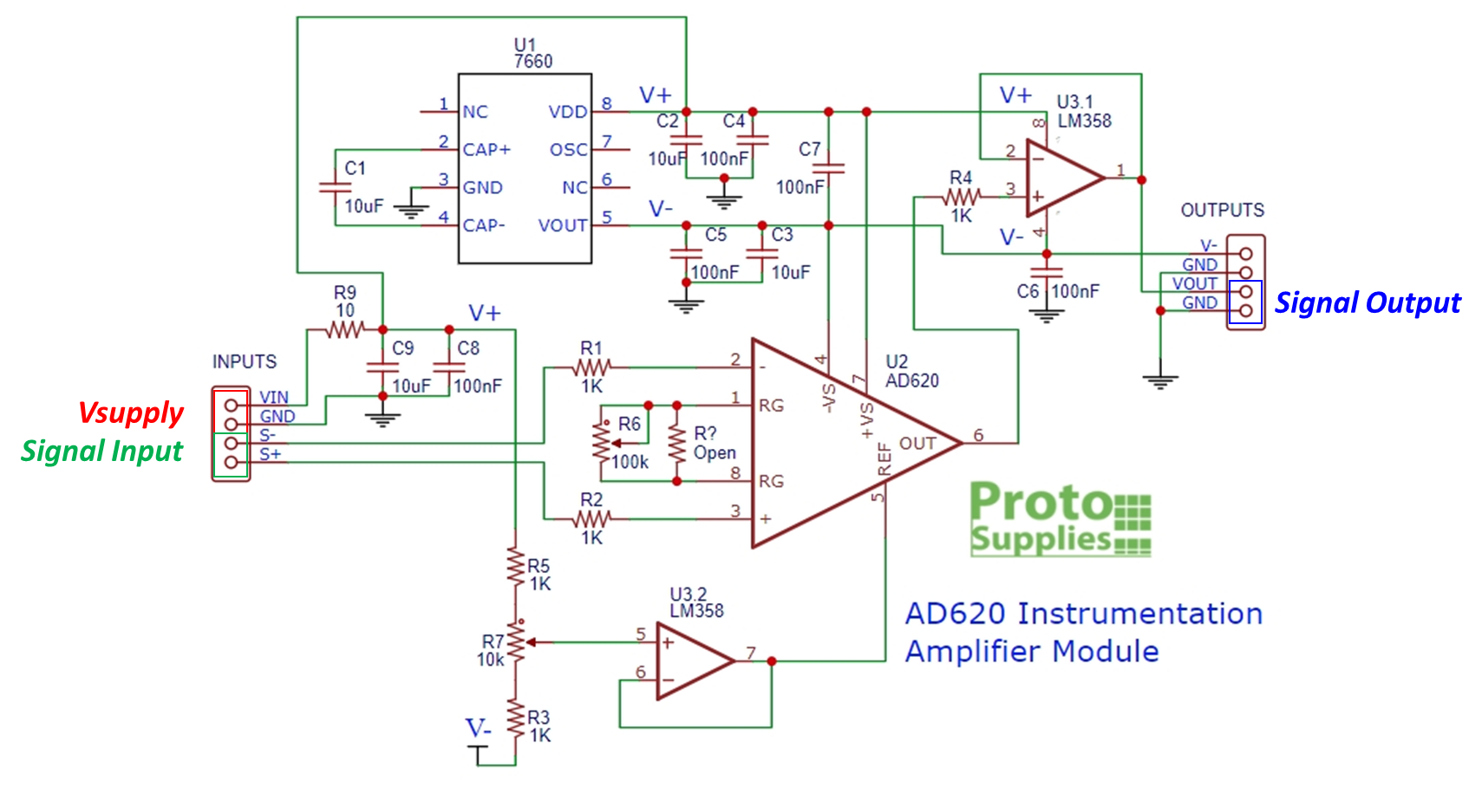
module schematic Souurce - https://protosupplies.com/product/ad620-instrumentation-amplifier-module/

A problem shows up when I'm testing the circuit and couldnt't find what cause it.

When only appling the Vsupply voltage and let Signal Input pin floating.

Configuration A

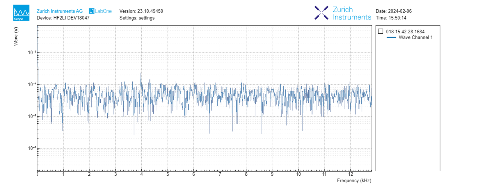
The frequency FFT result from Signal Output pin is shown below (Configuration A).

Configuration A FFT

The result is expected, a flat frequency band except DC signal (Maybe caused by Voffset of the amplifier).

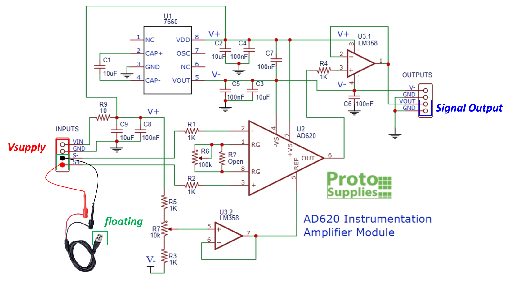
However, when I connect the "BNC to minigrabber cable" to Signal Input pin, and let the BNC terminal floating (Configuration B).

Configuration B

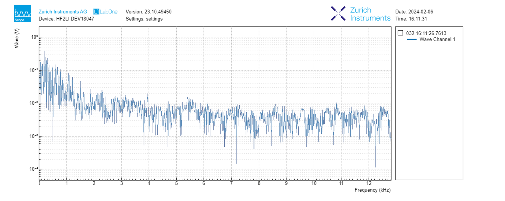
The FFT from Signal Output pin is changed as shown.

Configuration B FFT

There seems to be an unwanted signal into the BNC termanial and get amplified from AD620 module and the FFT band is not flat anymore.

My questions are

a) What cause the unwanted signal input to the AD620 module by just connecting a cable?

b) Is there any solutions or ways to avoid this situation?

Any suggestions would be very helpful to me!

Thanks

\$\endgroup\$
1
  • 1
    \$\begingroup\$ As already pointed out, at least, add 1 MOhm (or more) resistors at the two inputs (S+ and S-) wired to the ground. \$\endgroup\$
    – Antonio51
    Commented Feb 6 at 9:19

1 Answer 1

2
\$\begingroup\$

You are connecting "an antenna" to your input and, it is picking up extraneous electric fields from within your environment.

At the very least (for this test to have valid results), you should connect a low impedance to the ends of your coaxial cable.

Also note that the module you have purchased does not have bias-current-bleed resistors fitted on both inputs to ground and this will certainly exacerbate your experience.

In short, you are abusing the module in ways that are not technically acceptable.

\$\endgroup\$
2
  • \$\begingroup\$ Sorry, do you mean the module in my post could go better if I add a resistor from both signal input to gnd to provide a path for bias current? \$\endgroup\$
    – Jack Huang
    Commented Feb 7 at 2:33
  • \$\begingroup\$ Yes, it will work better when bleed resistors are added. \$\endgroup\$
    – Andy aka
    Commented Feb 7 at 8:34

Your Answer

By clicking “Post Your Answer”, you agree to our terms of service and acknowledge you have read our privacy policy.

Not the answer you're looking for? Browse other questions tagged or ask your own question.