0
\$\begingroup\$

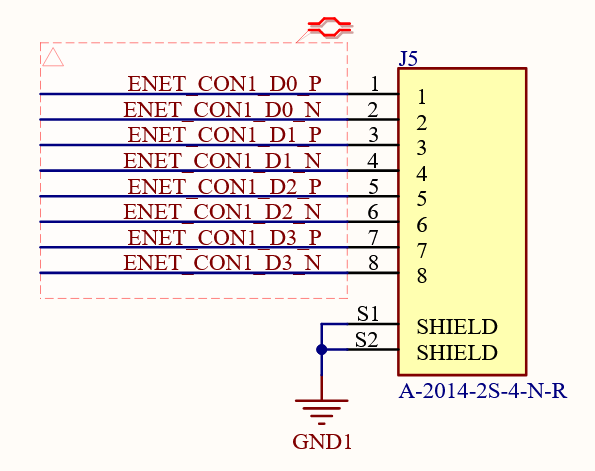
I designed a board recently that accidentally had an incorrect pinout on the RJ45 jack for Ethernet. Instead of following TIA568, I instead routed it straight-through:

RJ45 routed straight-through

Oh well, simple mistake, resolvable with a custom patch cable. But just for fun, I tried using a normal patch cable and connected it to a switch... And got a link?? Only a 100BASE-TX link instead of the gigabit link that I eventually wanted, but still, I was expecting no link at all with this messed up pinout!

I've seen a few features that can resolve typical cabling issues, such as:

  • Auto polarity inversion
  • Auto MDI/MDI-X
    • this can swap pairs A/B and C/D independently, but usually no other swaps.
  • Autonegotiation (mostly for the PHYs though)

However, my situation is that the pair on pins 1 and 2 is routed properly; that's one half of the 100BASE-TX connection. But then, the other half that should be on pins 3 and 6 is actually on pins 3 and 4. Since this results in the signal being split across pairs on the receiving side, I don't think that polarity inversion or auto-crossover could fix this.

And yet, despite this interface being clearly wrong, I still got a 100BASE-TX link! My question is, how? What mechanism allows for this incorrect pinout to wind up working somehow, albeit in a limited fashion? This has occurred across multiple models of PHY on my board and multiple test devices (switches, Ethernet cards, Ethernet adapters) so it doesn't seem to be an isolated event either.

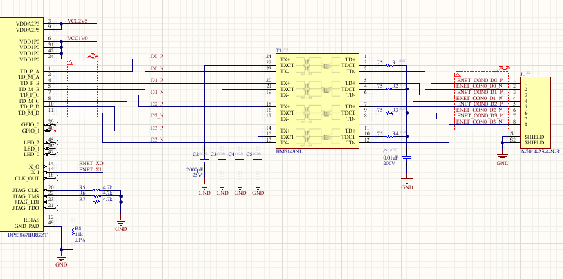
Full schematic from the PHY (a TI DP83867) to the problem port via the transformer: PHY schematic
\$\endgroup\$
5
  • \$\begingroup\$ Hard to say why it works, as most of the schematics that might reveal it is missing. Please post at least all connections between PHY IC and connector, also mentioning which PHY IC it is. \$\endgroup\$
    – Justme
    Commented Feb 20 at 19:13
  • \$\begingroup\$ @TypeIA How is that possible? The 100M link is kept up by sending IDLE symbol, which looks like any other control or data symbol on wire due to scrambling. \$\endgroup\$
    – Justme
    Commented Feb 20 at 20:26
  • \$\begingroup\$ @TypeIA yup, able to ping and iperf shows a bitrate of just under 100Mbit, so as far as I can tell, it's a fully functioning 100BASE-TX link. I can see that it advertises up to 1000BASE-T but the link itself negotiates down to 100BASE-TX \$\endgroup\$
    – Reid
    Commented Feb 20 at 21:00
  • \$\begingroup\$ @Justme added the schematic showing the phy-to-port connection. I don't think it has to do with the schematic since I've observed this across designs with different PHYs, but I'm happy to be wrong of course. And when the pinout is fixed with a rewired patch cable, I get a perfect 1000BASE-T connection as expected. \$\endgroup\$
    – Reid
    Commented Feb 20 at 21:08
  • \$\begingroup\$ @Justme I may be thinking of *MII links instead of the copper side; I withdraw the comment! I know from experience it can be in such a state in e.g. RGMII. In any case not the situation here. \$\endgroup\$
    – TypeIA
    Commented Feb 21 at 8:50

1 Answer 1

1
\$\begingroup\$

The connection is not obvious, but as the pair used for pins 3&6 share a path between two transfoŕmer center taps via two 75 ohm resistors, there must be good enough signal for the link to work.

\$\endgroup\$
1
  • \$\begingroup\$ Huh, Ethernet is really quite resilient! I tried removing the 75 ohm resistors, but the link persisted (probably due to the resistors in my laptop). I also tried getting a link with only pin 1, 2, and 3 connected, but that didn't work. I guess as long as you have a return path, Ethernet will figure the rest out, despite marginal conditions. \$\endgroup\$
    – Reid
    Commented Feb 27 at 15:28

Your Answer

By clicking “Post Your Answer”, you agree to our terms of service and acknowledge you have read our privacy policy.

Not the answer you're looking for? Browse other questions tagged or ask your own question.