4
\$\begingroup\$

I have an embedded system, that whenever the PHY transmits on the twisted pair, the connected hub indicates a collision, and I see nothing on Wireshark. I am 100% confident it is not a software problem, as almost identical (pin mux) code runs perfectly fine on the CPU's evaluation board. I have verified that the pin muxing is correct, and there is data on the RMII interface going to the PHY. The software is pretty simple and just attempts to ping an address.

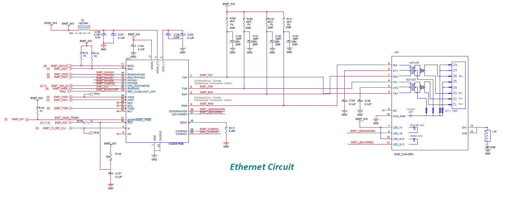
The PHY in question is the KSZ8081RNB. RJ45 + Magnetics.

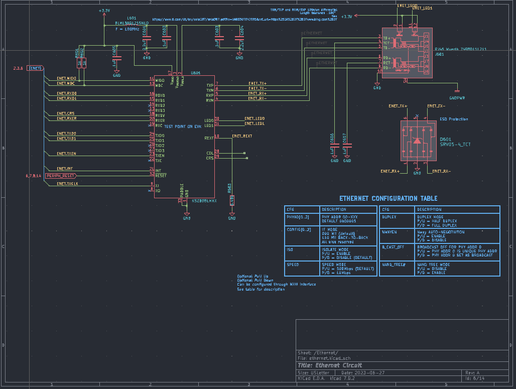
My Schematic: Schematic

Eval board Schematic: (I missed the TVS diode but it is not populated on the eval board)

Schematic for the CPU Eval Board

Datasheet for the Eval board magnetic

(Note that the part number I listed earlier is the correct one, we use the RMII interface not the full MII).

Testing setup: My board -> MDI Cable -> 10Mbps 1/2 duplex hub -> MDI -> PC with Wireshark. We have also tested this with a gigabit switch (as well as connected directly to the PC), and still indicated link and activity going out of the board. I would expect to see the ARP requests out of the board on Wireshark. We have also tried using an MDI-X cable, and getting a dump of the PHY registers confirms that it detected the crossover and corrected it (PHY supports auto MDI-X). In all cases, the link lights on both devices indicate that the link is up and there is activity on the line.

What could be causing this, or what am I missing?

UPDATE 9/15/23 AM PHY Registers

0 - 0x1000

1 - 0x786d

2 - 0x22

3 - 0x1561

4 - 0x1e1

5 - 0x20

6 - 0x4

7 - 0x2001

8 through 21 - 0's

22 - 0x1

23 - 0x3c01

24 - 0x801

25 - 0x7777

26 - 0x7777

27 - 0x1

28,29 - 0's

30 - 0x111

31 - 0x8180

Edit 9/15/23 PM - Scope captures. These were taken with 10Mbps 1/2duplex mode forced on the phy.
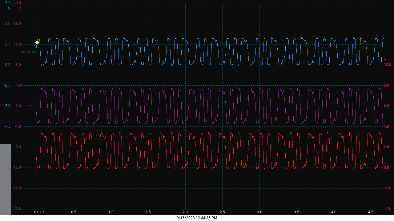
R=TX+ B=TX- P=R-B.R=TX+ B=TX- P=R-B. This is taken without any cable connected, by forcing register 0x1f bit 11 high.
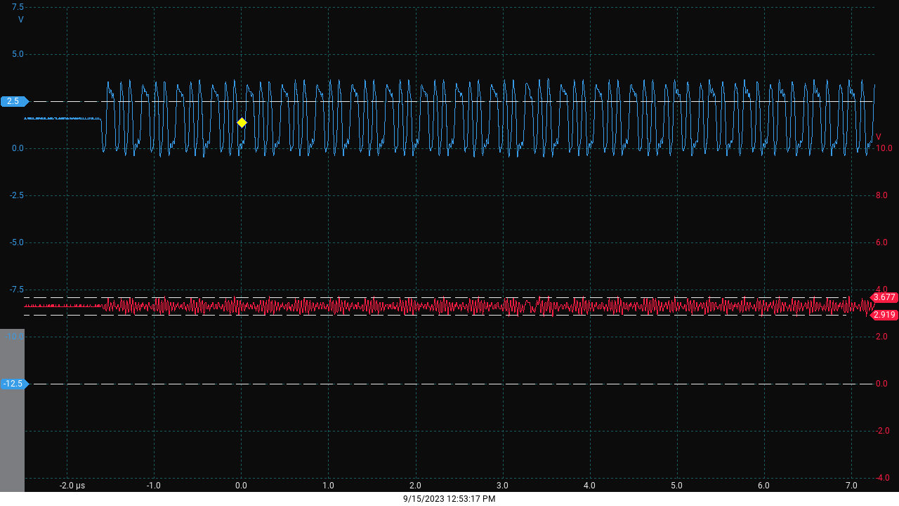
B=TX+ R=RX+B=TX+ R=RX+. Attempting to measure crosstalk/noise without cable connected (same settings as previous image). Roughly 750mVp-p of noise (which is only from my board + magnetics)
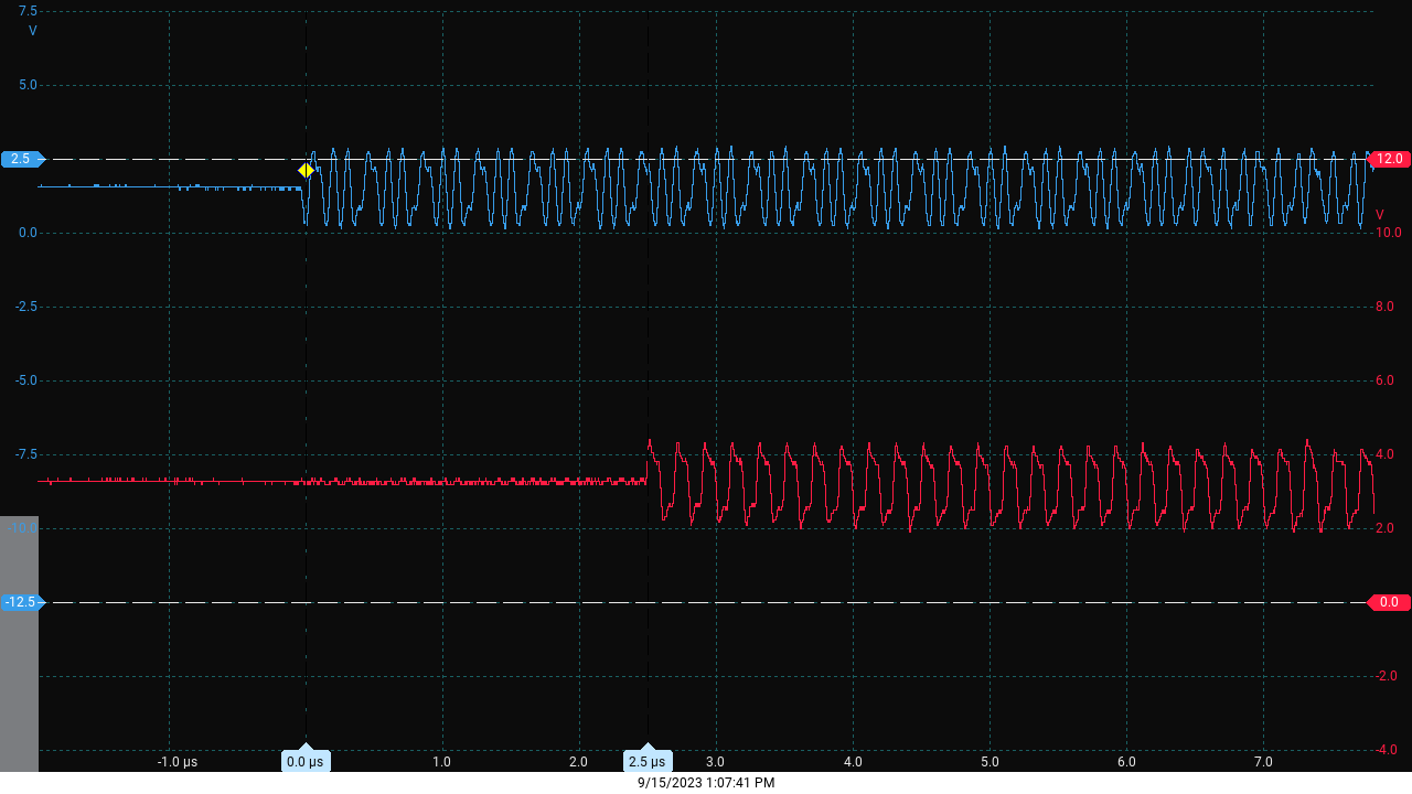
B=TX+ R=RX+B=TX+ R=RX+. For certain something is transmitting and causing a collision. The delay is roughly 2.5us. This was taken with the same 10Mbps hub that has been previously used.
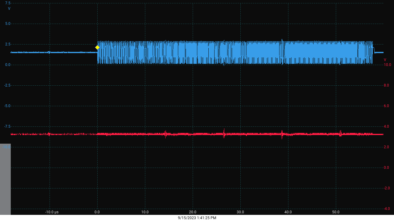
Same as previous image, but with switch This image taken with Gigabit switch. No phantom transmitter, but still no link. Settings are still 10Mbps 1/2 duplex.

\$\endgroup\$
8
  • 2
    \$\begingroup\$ Are there no resistors on the LEDs to limit current? \$\endgroup\$
    – Finbarr
    Commented Sep 14, 2023 at 19:56
  • 1
    \$\begingroup\$ @Finbarr That's odd indeed, especially for the eval board. I could not find anywhere in the manual that mentions current limits on the LED pins, and the datasheet explicitly shows the current limiting resistors in the examples. \$\endgroup\$
    – pipe
    Commented Sep 14, 2023 at 20:46
  • \$\begingroup\$ @Finbarr Good catch, I should probably add them for the next revision. However, using my Mk.1 Eyeballs, I don't think they're getting over-current, they're just a normal bright (in my opinion). I will add the option for them in the next revision though. \$\endgroup\$
    – Shaken_U
    Commented Sep 15, 2023 at 14:22
  • \$\begingroup\$ It's not clear what magnetics part was used on the eval kit, but it is clear that your pinout doesn't match the eval pinout. \$\endgroup\$
    – Ben Voigt
    Commented Sep 15, 2023 at 14:48
  • 1
    \$\begingroup\$ You described 6 test scenarios (10BT hub, 1000BT switch, direct-to-PC)x(normal, crossover). And described the results from one: collision detected by the 10BT hub. Do any of the scenarios have working data transfer? Does the PHY register dump show the correct speed and duplex have been negotiated? \$\endgroup\$
    – Ben Voigt
    Commented Sep 15, 2023 at 17:52

2 Answers 2

1
\$\begingroup\$

I'd check the power first thing, get a scope on the 3v3 power rail and make sure it looks ok. The next thing I'd check is the eye diagram and make sure the eye diagram has the appropriate voltage levels. Last thing would be to check the configuration pullup/pulldown straps and also power up sequence for the KSZ8081, make sure that the reset and power up sequence is working correctly.

\$\endgroup\$
2
  • \$\begingroup\$ 3v3 rail is clean, as is the 1v2 rail provided by the phy. The SDK example software does a software reset of the KSZ8081 as soon as it connects to it over MDIO. I have inspected the registers and did not see anything out of the ordinary. It said the link status was up and operating at the speed/duplex I expect. I don't have a differential probe but I will see what I can do tomorrow to get an eye diagram. \$\endgroup\$
    – Shaken_U
    Commented Sep 15, 2023 at 1:35
  • 1
    \$\begingroup\$ You can use two single ended probes and subtract at the speeds you have, if you don't mind some common mode noise \$\endgroup\$
    – Voltage Spike
    Commented Sep 15, 2023 at 3:11
0
\$\begingroup\$

It looks like the positive supply pin (pin 5) of the ESD protection diode array is disconnected. That should go to the 3V3 supply rail.

\$\endgroup\$
2
  • \$\begingroup\$ I missed it in my screenshot of the eval board, but that is not connected there either. Right now I haven't even populated the ESD diode so that should't be the problem either way \$\endgroup\$
    – Shaken_U
    Commented Sep 15, 2023 at 1:36
  • 1
    \$\begingroup\$ Good observation, but this is unlikely the reason of device failing to work. \$\endgroup\$
    – Justme
    Commented Sep 15, 2023 at 13:57

Your Answer

By clicking “Post Your Answer”, you agree to our terms of service and acknowledge you have read our privacy policy.

Not the answer you're looking for? Browse other questions tagged or ask your own question.