0
\$\begingroup\$

I'm building a multi device using canbus for communication and have a few questions.

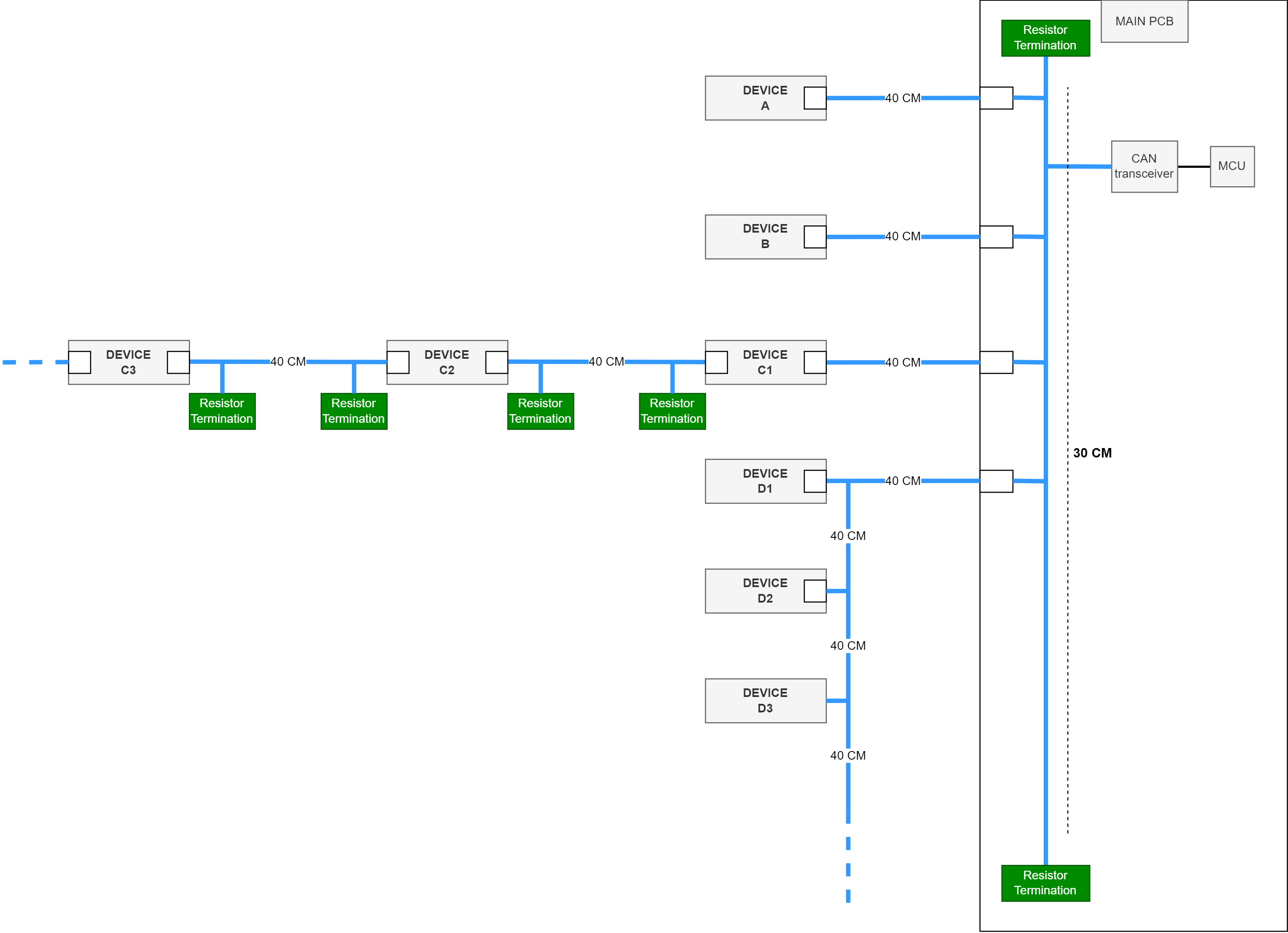
The image below illustrates my setup with multiple canbus wiring possibilities for devices. The big pcb called MAIN PCB have around a 30cm copper traces around the pcb and multiple connectors for devices to connect to directly to the can bus network. Added resistor termination directly to the MAIN PCB can bus because all the devices are optional to the network. All wiring also connects GND signal.

I was hoping to achieve up to 1Mbps using CAN 2.0B.

  1. There could be multiple Device type A/B using multiple connectors, each one up to 40cm stub. Can this be a issue?
  2. For devices type C/D, can both work or the D type add to much stub?
  3. For device C type, the idea is to avoid using too long stubs, each device would have 2 different can bus links and would route canbus packages between them. Daisy chaining them. Is this a good idea?
  4. What kind of connectors could be recommended in this example?

enter image description here

\$\endgroup\$
4
  • 2
    \$\begingroup\$ Are all blue lines intended to be the same CAN bus network or is C1/C2 a gateway? \$\endgroup\$
    – Jeroen3
    Commented Mar 4 at 12:58
  • \$\begingroup\$ C1/C2 are like a gateway, they have 2 transceivers/can controllers. \$\endgroup\$ Commented Mar 4 at 13:57
  • 1
    \$\begingroup\$ Generally, in my personal experience, you will get away with very long stubs on CAN if you just keep the baudrates down. 125kbps or 250kbps are the most common baudrates and they are quite lenient to stubs. For 1Mbps it gets pickier overall though. Is there an actual real-time reason you want to use 1Mbps? How did you come up with that baudrate? \$\endgroup\$
    – Lundin
    Commented Mar 4 at 14:46
  • 1
    \$\begingroup\$ As for connectors, it does of course depend on your environment, budget, IP requirements and so on. There's a whole lot of different connector pin-outs specified by the CANopen standard, everything from RJ45 to M12. \$\endgroup\$
    – Lundin
    Commented Mar 4 at 14:47

2 Answers 2

1
\$\begingroup\$
  1. Suggestion for 1 Mbps bus is to keep stubs max 30cm. These cables are 40cm long so they exceed the suggestions.

  2. In case of devices D being chained like that, it is not a stub but the main branch of the bus because it is the longest. Which means end of that branch must be terminated, not your main board, which is now the stub.

  3. In case of devices C, they could just be again be the main long bus branch, which should be terminated at the end.

  4. Any connector otherwise suitable for 1 MBps CAN. There is no specific or generic CAN connectors or pinouts. You could use a 3.5mm TRS plug if you want. Or 8P8C modular jacks so you can use CAT5 cables. DE-9 or M12 are often seen too.

\$\endgroup\$
1
\$\begingroup\$

Instead of running your CAN backbone through the PCB it should be an external cable with a terminator at each end.

All of the devices should be teed off the backbone with 30cm or less stubs.

This overcomes the distance restriction which necessitates your feed through devices. Your main PCB becomes just another device teed off the backbone.

There is no specific connector for CAN select something with the required number of conductors and preferably something that has a T connector for connecting your devices to the backbone.

\$\endgroup\$

Your Answer

By clicking “Post Your Answer”, you agree to our terms of service and acknowledge you have read our privacy policy.

Not the answer you're looking for? Browse other questions tagged or ask your own question.