0
\$\begingroup\$

Ref:
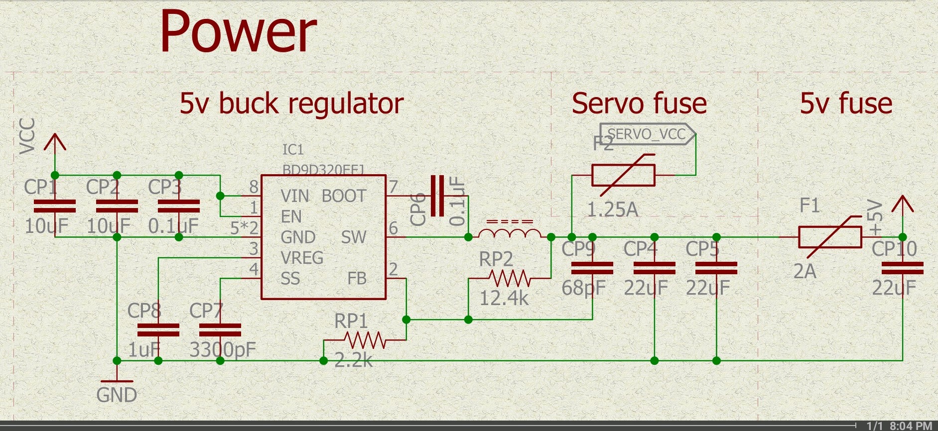
The following schematic:

GoPiGo-3 5v buck converter schematic

Background:
This circuit is part of a controller board for a Raspberry Pi controlled robot and this circuit supplies the +5v to the Raspberry Pi through its GPIO pins.

Since later versions of the Raspberry Pi have a higher current requirement than the controller can supply, I have been supplying additional +5v power via the Pi's power input connector.

Since I can supply more power using the external source, I adjust it to be slightly higher than the +5v supplied by this circuit so that the external power supply provides power unless the demand is particularly high, than this circuit, part of the controller, can help supply the load.

  • The input voltage (VCC) is +12v supplied by a MOSFET switched external battery source. (Pressing the robot's power button enables the +12v VCC voltage.)

  • The external power source is the output of an external variable voltage buck converter board set to +5.2v(±).  The output is connected to the Raspberry Pi via a USB cable isolated with a high-current Schottky diode and the input is the same battery that runs the rest of the robot.

  • I deliberately overdrive the output of the on-board buck converter by a couple of tenths of a volt with the idea that it won't contribute power unless the external power supply is insufficient.

My thought was that by overdriving the output, the on-board supply would just shut down until needed.

The problem:
When the output of the external supply is set higher than the nominal output of this circuit, the input voltage skyrockets to as much as 20v! (Which is in excess of the maximum VCC of 16v.)

I mitigated this by isolating the output going to the Raspberry Pi with another Schottky diode. Unfortunately, this drops the output voltage by 0.4v down to 4.6v, which causes any attached devices to fail to start.

Questions:

  1. Why does this happen? (The datasheet is totally silent on the issue of overdriving the output.)

  2. Assuming that the isolation diode is necessary, what values should I substitute for the voltage programming resistors, (RP1 and RP2) to bring the output on the other side of the isolation diode to 5v again?

\$\endgroup\$

1 Answer 1

1
\$\begingroup\$

This happens because your converter is a synchronous buck.

It's quite happy with negative inductor current, and when you put a voltage on the output higher than the regulation target it will try to regulate that voltage back down to your target by drawing current from the output.

See this question.

It acts as a boost converter, pushing the energy back to the input and if the input can't absorb it the input voltage will rise as you noticed.

You can diode-or the outputs of your supplies, maybe compensating for the diode drop by adjusting your output voltage (check tolerances, etc), or you can use an ideal diode or-ing solution to mitigate the issue. Or maybe re-architect the system to use a single supply capable of supplying all the current needed.

You could try changing RP2 to 13K to get 5.29 V out nominal or around 5.46 V max with tolerances, but note that it will change with load so be sure at very light load that 5.46 V won't damage anything downstream. (See here for a quick way to calculate feedback divider resistors.)

\$\endgroup\$
5
  • \$\begingroup\$ What would happen if the top of the two feedback resistors were put at the output of the isolation diode? Would that let all the magic smoke out? Would it regulate the output at the diode to +5? \$\endgroup\$ Commented Sep 27 at 6:47
  • \$\begingroup\$ Since this is a commercially available device, "re-architecting the circuit" to accommodate the extra current needed isn't really an option - though there are a number of changes I'd LOVE to make. P.S. I've done several "cut-and-jumper" mods to the circuit already. (:wink:) forum.dexterindustries.com/t/… \$\endgroup\$ Commented Sep 27 at 9:54
  • \$\begingroup\$ Putting the feedback after the diode is opening the feedback loop during times when the control loop wants to sink current. This doesn't just happen when the output is overdriven, but during load transients and load releases. So it's likely to cause instability and erratic transient performance. \$\endgroup\$
    – John D
    Commented Sep 27 at 15:57
  • \$\begingroup\$ As for the re-architecting, I did have cuts and jumpers in mind, or removing parts to jumper in a bigger supply. But I'm not familiar with what you're working with, so if it's not an option then the diode isolation might work. \$\endgroup\$
    – John D
    Commented Sep 27 at 16:00
  • \$\begingroup\$ Good to know, that this IC is operating in two quadrants! I just was looking for such a buck converter. Most converters prohibit this internally. \$\endgroup\$
    – Jens
    Commented Sep 28 at 19:56

Your Answer

By clicking “Post Your Answer”, you agree to our terms of service and acknowledge you have read our privacy policy.

Not the answer you're looking for? Browse other questions tagged or ask your own question.