0
\$\begingroup\$

I purchased an inexpensive electric hoist off Amazon with the intention of partially replacing its control circuits so that it can controlled via ESPhome.

There are only 2 buttons on the control box. This hoist has 3 operating modes:

  1. Off (no button pressed)
  2. Forward (Forward button pressed)
  3. Reverse (Reverse button pressed)

Here are pictures of its existing control circuit: enter image description here
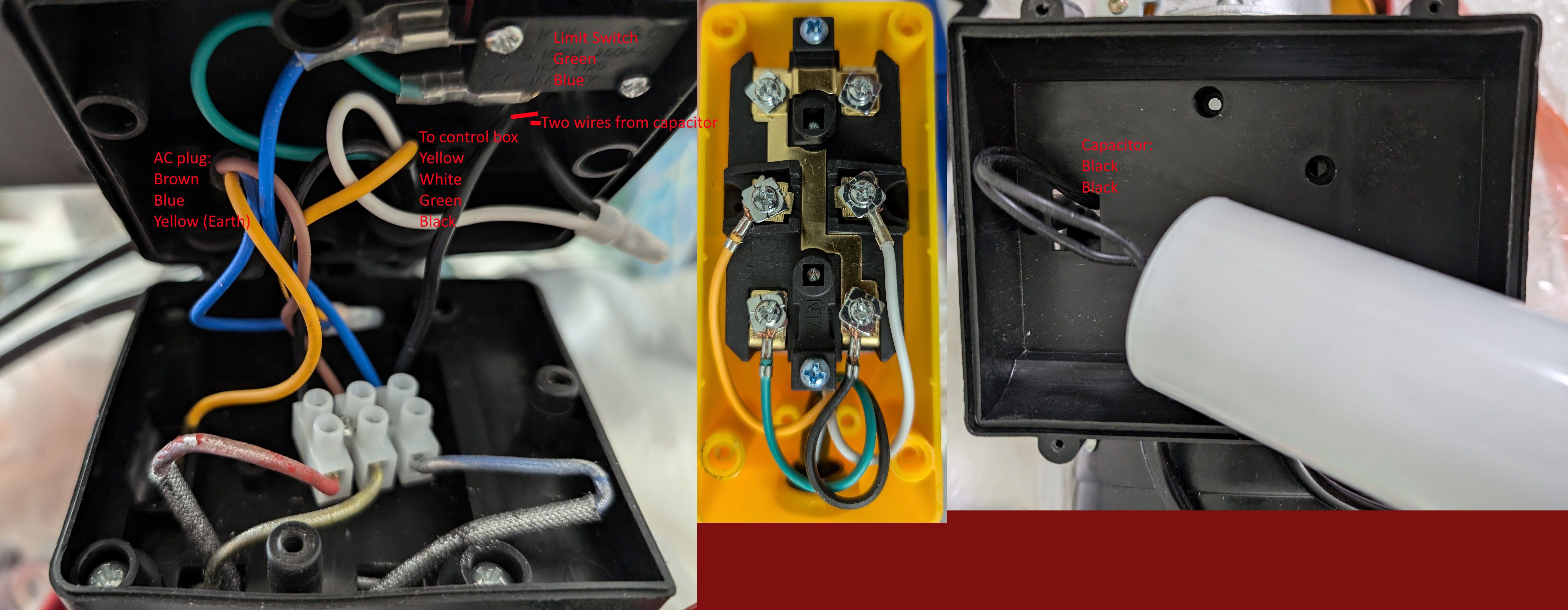
I believe the AC motor is a Permanent-split capacitor motor based on how the capacitor is permanently wired to one of the motor winding in series.

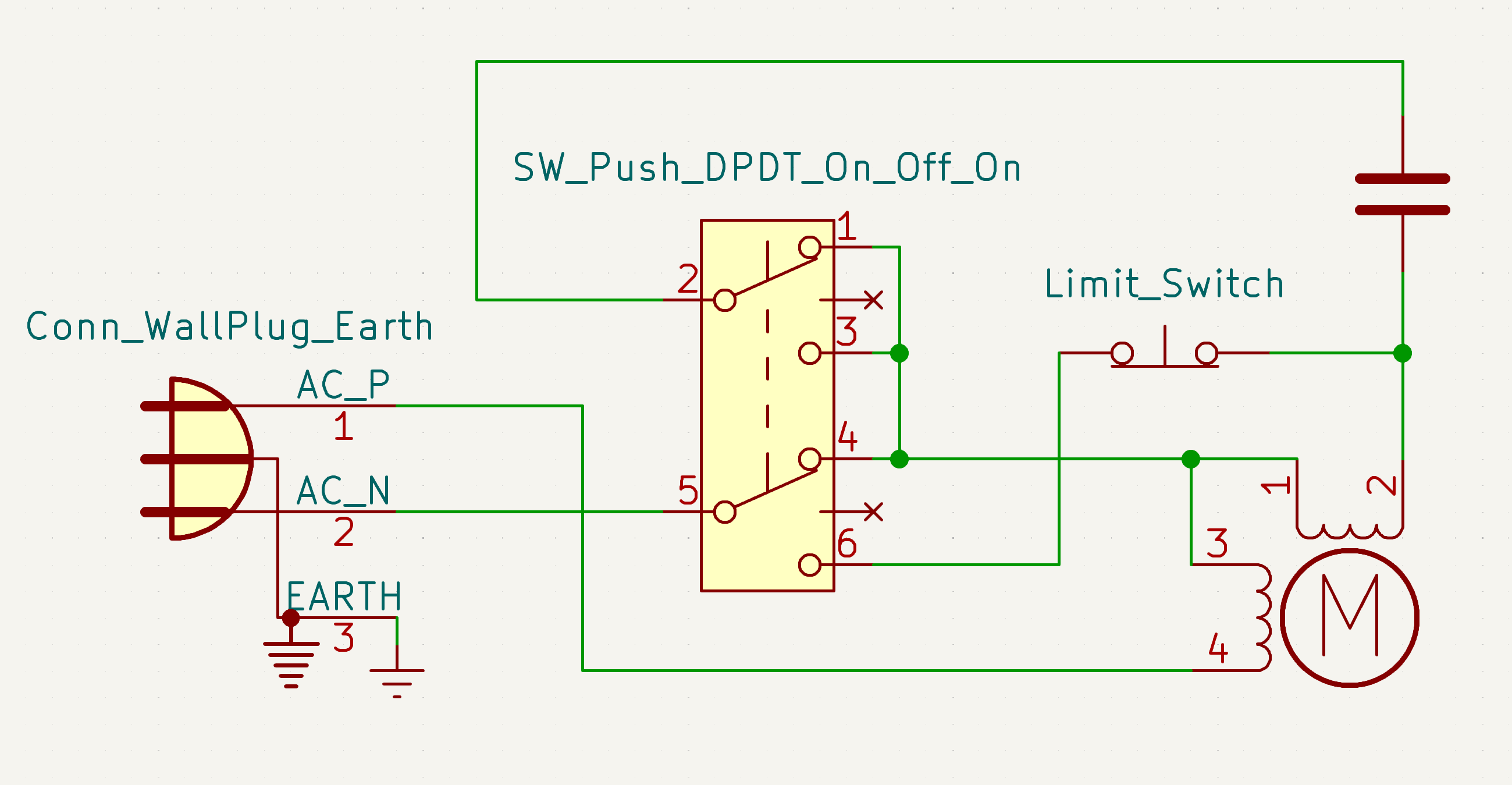
Based on the above photos, I drew the following schematic:

enter image description here

Does this schematic look correct? I am very unsure about it.

Since the original control circuit uses a single DPDT On-Off-On switch, I just assumed (without much evidence) that it can be replaced by two SPDT relays.

But when I sit down to actually draw the the new relay control schematic, I become stuck. I am struggling to find a way to replace the original one DPDT On-Off-On switch with two SPDT relays.

If I relax the restriction and allow myself to use 3 relays, then the problem becomes easy again, but a two relay would be more elegant if it is indeed possible.

\$\endgroup\$
3
  • 1
    \$\begingroup\$ A three position push switch? How does that work, exactly? \$\endgroup\$
    – Finbarr
    Commented Jun 26 at 13:14
  • \$\begingroup\$ It's kinda hard to explain using words, so here is a datasheet for an equivalent device. Basically take a two-pole, 3-throw rocker switch, and remove/ignore the middle throw (off position), then expose the two ends of the rocker as separate push buttons. \$\endgroup\$ Commented Jun 26 at 21:18
  • \$\begingroup\$ @Finbarr Here is another equivalent device. Their description is on the mark: "DPDT On-Off-On, Functions like two separate SPDT switches operated by the same actuator. Only two loads can be On at a time. " \$\endgroup\$ Commented Jun 26 at 21:22

2 Answers 2

1
\$\begingroup\$

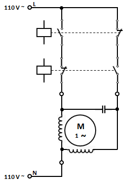
The application would require two single-phase, 110 V ~, 12 A, AC-7B duty, modular contactors with 24 V DC coil and (1 NO + 1 NC) contacts.

Here's the schematic.

enter image description here

The limit switch is not shown.

\$\endgroup\$
2
\$\begingroup\$

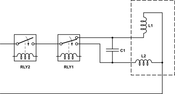
I don't think your schematic is right- the top switch would do nothing.

Something like the below is what I expect could work (limit switch(s), thermal protection etc. not shown):

schematic

simulate this circuit – Schematic created using CircuitLab

\$\endgroup\$
3
  • \$\begingroup\$ the top switch turn the motor off in the middle position \$\endgroup\$ Commented Jun 26 at 12:07
  • \$\begingroup\$ The connection is already broken from the bottom switch. \$\endgroup\$ Commented Jun 26 at 12:22
  • \$\begingroup\$ ah yeah, it is. maybe it has something to do with operating the brake? \$\endgroup\$ Commented Jun 26 at 12:36

Your Answer

By clicking “Post Your Answer”, you agree to our terms of service and acknowledge you have read our privacy policy.

Not the answer you're looking for? Browse other questions tagged or ask your own question.