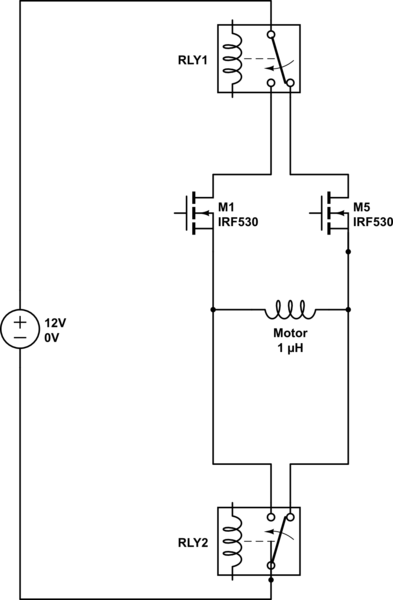
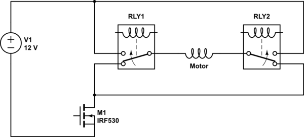
I'm relatively new to using motors and electronics, and wanted to know if this was possible. I am trying to understand the motor circuit of a PCB I am analyzing. The PCB doesn't use a FET H-Bridge but rather two SPDT relays. I realized however that with this configuration you cannot use PWM to control speed. It may still be functional, however, because the application only uses a high speed setting (12V) and a low speed setting (5V) which could come from either the 12V battery or the 5V MCU they use to power the motor. However, the motor draws more current under higher resistance, which decreases voltage, showing constant power. From that I concluded that PWM isn't possible, though I am unsure if that is a sound assumption. There is also on the PCB two identical N channel mosfets that are close by, which my instincts tell me are for the motors as well.
My questions are as follows:
- Is it possible the relays and mosfets follow the schematic I've made below? Does it make sense?
- If it does make sense, how would you configure the flyback diodes to protect the circuit?

simulate this circuit – Schematic created using CircuitLab


