1
\$\begingroup\$

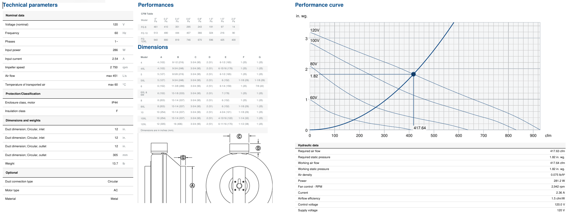
I am using a 120 V AC fan in my application, with a speed control circuit connected to it, and I'm controlling the fan motor using a PWM signal through software. When operating the fan at 100% speed, it runs perfectly fine, but if I run the fan at 35% to 50% speed, it stops working after about 45 minutes because the fan's internal thermal switch opens. Could someone please review my speed control circuit and the fan specifications?

I suspect the issue may be due to an improper switching method or incompatibility of the pulse signals. I would appreciate any guidance on improving the circuit, possibly with a better photovoltaic switch or TRIAC. I’ve tried measuring the TRIAC gate signal and the voltage at pin 1 of the photovoltaic SSR at both 0% and 45% speed using an oscilloscope, but I haven’t been able to identify the problem.

  • At 50% speed, I got 2.25 V DC from PWM signal wire.
  • TRIAC mfg P/N: BTA08-4008
  • Photovoltaic relay P/N: PVT412L

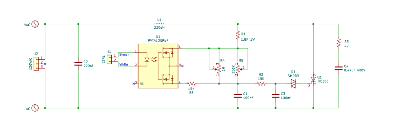
Speed control ckt: enter image description here

Fan specification:

enter image description here

\$\endgroup\$
3
  • 3
    \$\begingroup\$ The answer in "Can a Solid-State Relay Control AC Powered Fan Speed Via PWM" indicates potential issues with trying to control an AC fan using PWM. Is your PWM synchronised to the AC cycles? \$\endgroup\$ Commented Sep 7 at 21:40
  • \$\begingroup\$ The statement Motor type AC falls short of being illuminative. I think the RPM low for an induction machine@60 Hz, power factor low for a universal machine that size. \$\endgroup\$
    – greybeard
    Commented Sep 7 at 22:27
  • \$\begingroup\$ Does the fan also overheat if you control the speed only with R4 or R5 without a PWM signal? \$\endgroup\$
    – Jens
    Commented Sep 8 at 12:08

4 Answers 4

1
\$\begingroup\$

I guess it is due to a bad switching/control circuit, it is a nice idea the circuit you proposed, but it wouldn't work with pwm input sadly, there is an appropriate driving circuit (using Phase Control) that will be explained below, but first, let's look at the triac.

TRIAC

A TRIAC cannot be turned off using the control voltage once it has been triggered (turned on) during a half-cycle of the AC waveform. Instead, it remains on until the current through it naturally drops below a certain threshold (the holding current), which usually happens when the AC voltage crosses zero (the zero crossing point).

In other words:

  • Once the TRIAC is turned on, it conducts for the remainder of the AC half-cycle.
  • It can only turn off when the AC voltage reaches zero (during the natural zero crossing).
  • To control when it turns on again, you need to manage the triggering at each half-cycle.

If the TRIAC is not switching efficiently, it might be contributing to improper voltage or current regulation at lower speeds. For example, if the TRIAC is not turning on and off properly due to poor gate triggering from the PWM signal, it could lead to improper current flow and increased heat dissipation.

Ripple Current

When operating at lower speeds, especially with AC motors, high ripple current can cause significant heating in both the motor windings and the TRIAC. This can overload the fan’s thermal protection if not properly managed.

Ripple current refers to the AC component of the current that "ripples" on top of the average (DC) current, particularly when a switching power supply or PWM control is involved. It’s important in motors because large ripple currents cause extra heating and stress on the windings and components.

Why Increasing PWM Frequency Won't Help:

Once the TRIAC is triggered, it will conduct until the current reaches zero, regardless of how fast the PWM signal is switching.

If the PWM frequency is too high, you could end up attempting to trigger the TRIAC multiple times within a single AC half-cycle, but it would have no effect, since the TRIAC is already on. This makes high-frequency PWM ineffective for precise control with TRIACs.

Proposed Solution:

You can control the phase angle at which the TRIAC is triggered in each AC cycle. By delaying the TRIAC's turn-on point relative to the AC zero crossing, you control the amount of power delivered to the load (motor). This is the standard approach for dimming lights or controlling motor speeds using a TRIAC.

There are many methods to implement this circuit, either by using microcontrollers or without them. Below is a simple phase control circuit example without microcontrollers: enter image description here

Circuit Operation:

  • Initial Condition: When the AC voltage starts a new half-cycle, the capacitor C1 begins to charge through the resistors R1 and R2.

  • Capacitor Charging: The charging time of C1 is controlled by the resistance values of R1 and R2 . As the capacitor charges, the voltage across it increases.

  • DIAC Triggering: Once the capacitor voltage VC1 reaches the breakover voltage of the DIAC (D1), the DIAC turns on. This discharges C1 rapidly and sends a current pulse to the gate of the TRIAC (Q1). The TRIAC is then triggered into conduction.

  • TRIAC Conduction: After the TRIAC is triggered by the gate pulse, it remains on for the rest of that AC half-cycle. The TRIAC will turn off only when the current through it drops below the holding current, which happens at the next zero crossing of the AC voltage.

  • Phase Control: The moment the TRIAC is triggered (relative to the AC cycle) determines how long it stays on during each half-cycle. Adjusting the resistance values (usually using a potentiometer) is the point at which the DIAC fires can be changed, thereby altering the amount of power delivered to the load. This is how the circuit controls the phase angle.

Additionally, if you would like to take control over with a microcontroller you would need to implement some zero-crossing detector circuit to sync the control signals with the AC power supply.
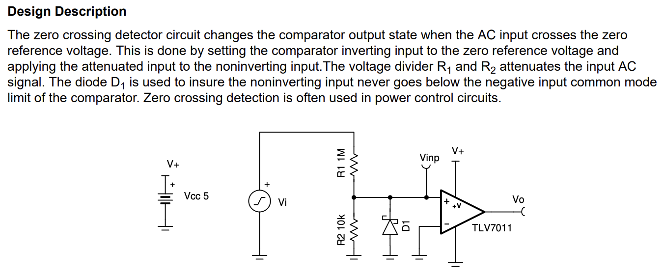
enter image description here

full doc: https://www.ti.com/lit/ab/snoa999/snoa999.pdf?ts=1726615394606

\$\endgroup\$
8
  • \$\begingroup\$ Hello Sir, Thank you for the detailed explanation. Based on your input, it seems we are indeed dealing with bad switching, and I believe we are using phase control circuit option, which I previously shared in my schematic diagram. Unfortunately, I am unable to pinpoint the exact problem within this circuit. Could you kindly assist in identifying potential areas of improvement? Whether it's selecting better components or any other direction to resolve the issue, I would greatly appreciate your guidance. Looking forward to any suggestions or recommendations you may have to help us \$\endgroup\$
    – JEH
    Commented Sep 9 at 17:44
  • \$\begingroup\$ Hi @JEH, after reviewing your circuit, nothing stands out as problematic. The issue likely lies with the driving signal. If you're using a PWM signal, remember: a) It must be synchronized with the AC phase. b) It should match the AC frequency (50 or 60 Hz, depending on your location). If you're using a microcontroller for PWM generation, I recommend implementing a Zero-Crossing detector to sync the microcontroller with the AC mains. \$\endgroup\$ Commented Sep 10 at 16:38
  • \$\begingroup\$ You can also: - Measure the gate voltage of the TRIAC when the circuit should be triggering to ensure it's getting sufficient gate current. - Ensure the control signal is correctly modulating the TRIAC by checking with an oscilloscope. - Check for any short circuits or incorrect component placements on the PCB. \$\endgroup\$ Commented Sep 10 at 16:39
  • \$\begingroup\$ Hello cheche, Yes, the PWM signal is coming from the manometer, which is operated through the software. Would you happen to have a sample circuit for a zero-cross detector that I could use as a reference? I’d like to modify it to fit my system. Your help is much appreciated, and I look forward to any suggestions or circuit examples you can share \$\endgroup\$
    – JEH
    Commented Sep 17 at 12:46
  • \$\begingroup\$ ti.com/lit/ab/snoa999/snoa999.pdf?ts=1726615394606 \$\endgroup\$ Commented Sep 18 at 3:11
0
\$\begingroup\$

PWM would not work on AC with a triac. Reason when the triac is triggered it will continue to conduct until it is commentated or the current crosses the minimum holding (zero cross) current. The triac can be turned on twice the AC frequency IE positive and negative half of the sine wave. This will starve the motor for energy. Try using a VFD (Variable Frequency Drive). The motor's speed is controlled by the line frequency not voltage.

By lowering the voltage the motor is trying to maintain speed based on the line frequency and will draw more current to maintain that. This causes an increase in heating. As I understand it if the current doubles, the heat will increase four times. From what I can tell the motor is also cooled with the airflow slowing the fan will also reduce cooling.

\$\endgroup\$
1
  • \$\begingroup\$ Hello Mr. Gill, Thank you for your valuable input on this matter. For this particular design, we are unable to use a VFD separately, as we need to control the motor speed remotely through software. Given this requirement, could you suggest alternative solutions for improving the current speed controller circuit? I would appreciate any recommendations on better component selection or potential design changes that could help resolve the issue. Your guidance would be greatly appreciated as finding a solution \$\endgroup\$
    – JEH
    Commented Sep 9 at 17:26
0
\$\begingroup\$

The simplest way to deal with your situation is to use a solid-state relay that can turn off independent of conduction angle:

schematic

simulate this circuit – Schematic created using CircuitLab

You may need some circuitry between the Microcontroller and the relay to match the voltages if they operate on different voltages (but finding SSR's that operate down to 3V isn't that hard).

But a simpler thing to try first before the SSR: Since your circuit works at the full speed with out trouble, you may want to try lowering the switching frequency to something unusually low (let's say 2Hz-10Hz). Doing this makes the edges/transitions (where the heating is taking effect) an insignificant temporal portion of the full switching period (500ms @ 2Hz).

This technique will work best if you have a large (high-inertia fan) to smooth out the torque ripple presented by the low switching frequency. For a fan, this is almost always acceptable - the exception would be if this fan was modulated in a precision airflow application.

In either case, I suggest a low switching frequency. In the SSR case, you could get by with a higher switching frequency. I've done this in the past with 10Hz, but I had a large fan (500CFM, or 14 m^3/min) so it work great for my application. YMMV.

\$\endgroup\$
0
\$\begingroup\$

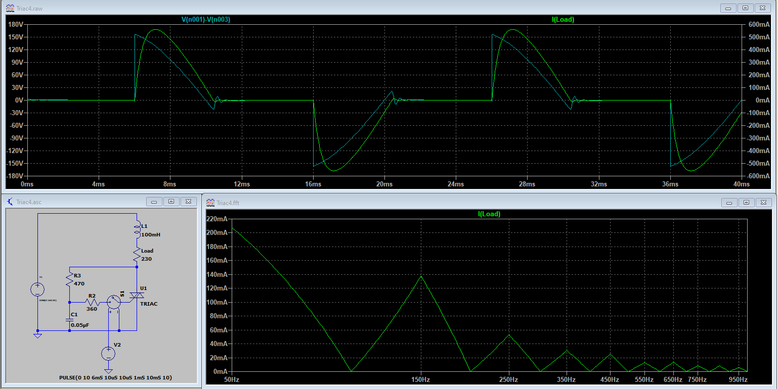
You control timing have been not stated, but I guess it can be phase control as other answers have pointed. This is used in many dimmers for bulbs or heating, but some issues come up with motors. This is the current shape with some inductive load, something similar as an induction motor. Once the triac if switched on, it will be latched until the current cross by zero. If you check the wave, you can see a high content of 3rd, 5th and 7th harmonic. These harmonics will increase heating in iron and windings, also in rotor, comparing with a sinusoidal wave, and could be the reason why your thermal sensor is tripping.

enter image description here

It could be also that in low speed, air flow is not enough for the motor and overheating could happen, but datasheet shows the curves at that speed. To be sure, a good test should be to feed the fan with a transformer to reduce voltage at 40..50% during a long time. A variac is a perfect tool, also a transformer from an hifi amp coul be used (they deliver about 2x30 V); another choice is a 230/115 V transformer, but with the primary feeded with 120 V, so you will get around the half.

Possible solutions should be use a low filter to reduce harmonics, not easy to design. Another approach are VFD, some of them can operate with 1ph motors, and can be remotly controlled. About SSR, the some harmonics will be present with`phase control, in case you use PWM, inductive peak will also be an issue.

\$\endgroup\$

Your Answer

By clicking “Post Your Answer”, you agree to our terms of service and acknowledge you have read our privacy policy.

Not the answer you're looking for? Browse other questions tagged or ask your own question.