0
\$\begingroup\$

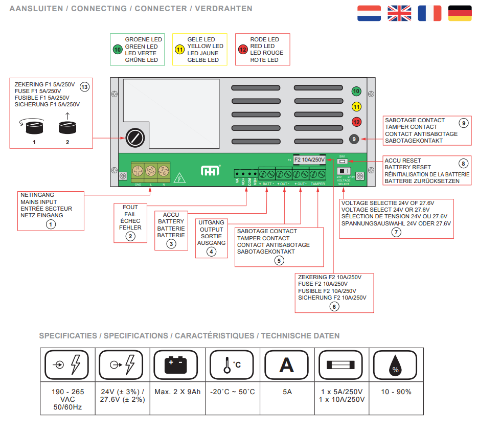
For my job I sometimes have to install an electromagnetic door lock. This comes with a power supply (24 V, 5 A), depicted in its manual thusly:

enter image description here

I understand that 220 V (for the Netherlands) powers this power supply, and outputs 24 V, 5 A.

My first question is: in the specifications you can see a magnet logo, and “1×5 A / 250 V” and “1×10 A / 250 V”. What does this mean, because all the magnets run on 24V, none of them run on 250V.

As I understand, voltage must be equal on the supplier and the supplied (power supply outputs 24 V, magnet must be 24 V), but the amperage can be different, but in one way: the amperage of the device (or devices) must not exceed the supplied amperage (in this case 5A). So why does it say “1×10 A” when the power supply outputs only 5 A?

As there are two outputs, my assumption is that either output has 24V 5A. There is no mention of this in the manual, and the customer service of the manufacturer is not helpful at all, but could it be that you can somehow combine to the two outputs and have 5 A + 5 A = 10 A?

The magnets that are used with this power supply run on 24 V, 1.25 A switch-on voltage and 275 mA continuous voltage. Is it then true that I can have (5000 mA / 275 mA) = ~eighteen 24 V electromagnetic locks? Or should I look at the switch-on voltage (5 A / 1.25 A) and have four 24 V electromagnetic locks?

You could also get a 12 V power supply and have a magnet with 12 V, 1.5 A switch-on voltage, and 550 mA continuous. Why would I choose a 12 V over a 24 V power supply? You could argue it would less cost to run, but why then not use the more cost-efficient one?

Thank you.

\$\endgroup\$
4
  • \$\begingroup\$ I'm not 100% sure but I think the magnet logo you're seeing is a fuse. Fuses are rated at a current for a given voltage. Having said that I don't know why it would specify both 10A and 5A.. Edit: OK i'm now sure it's a fuse because the other fuse ratings are too coincidental. We can already see that Fuse F1 needs to be 5A and Fuse F2 needs to be 10A. So I assume they mean "you need a 5A 250V fuse and a 10A 250V fuse" \$\endgroup\$
    – QuickishFM
    Commented Oct 5 at 16:40
  • \$\begingroup\$ I learned something: it's a fuse, not a magnet. Makes sense, yes, but that logo looks a lot like the magnet they have! \$\endgroup\$
    – Piet Er
    Commented Oct 5 at 16:46
  • \$\begingroup\$ @PietEr you can see a magnet logo ... almost everything in the picture is numbered ... please use the reference numbers \$\endgroup\$
    – jsotola
    Commented Oct 5 at 17:02
  • \$\begingroup\$ @jsotola You are absolutely right. The specification section is not numbered though, and was elsewhere in the manual. I know I know, should have made the connection, my brain refused. Lesson learned. \$\endgroup\$
    – Piet Er
    Commented Oct 6 at 17:07

3 Answers 3

0
\$\begingroup\$

My first question is: in the specifications you can see a magnet logo, and "1x5A/250V" and "1x10A/250V". What does this mean, because all the magnets run on 24V, none of them run on 250V.

That's the symbol for a fuse. The black boxes are the end caps, the outline rectangle is the glass tube and the line across the middle is the fuse wire.

It looks like there are two fuses: one for the mains and one for the low voltage.

As I understand, voltage must be equal on the supplier and the supplied (power supply outputs 24V, magnet must be 24V), but the amperage can be different, but in one way: the amperage of the device (or devices) must not exceed the supplied amperage (in this case 5A). So why does it say "1x10A" when the power supply outputs only 5A?

The fuse is there to protect against gross overload. To prevent nuisance fuse blowing and problems with current surges a higher rated fuse is chosen - often the next standard size up.

The fuse voltage is the voltage at which the fuse can be guaranteed to break the circuit when it blows. In simple terms, it is a guarantee that when the fuse melts the gap will be large enough that current in the form of an arc can't jump the gap. 250 V is required for the mains. A lower voltage would do for the low voltage but may cause confusion when only 250 V type are commonly available.

As there are two outputs, my assumption is that either output has 24V 5A. There is no mention of this in the manual, and the customer service of the manufacturer is not helpful at all, but could it be that you can somehow combine to the two outputs and have 5A + 5A = 10A?

The manual or label should state that. I'd open it up to see if there are relays controlling the output and, if there are, what the contacts are rated at.

The magnets that are used with this power supply run on 24V 1,25A switch-on voltage and 275mA continuous voltage [do you mean "current"?]. Is it then true that I can have (5000mA / 275mA) = ~eighteen 24V electromagnetic locks? Or should I look at the switch-on voltage (5A / 1,25A) and have four 24V electromagnetic locks?

Your calculations look right.

You could also get a 12V power supply and have a magnet with 12V 1,5A switch-on voltage, and 550mA continuous. Why would I choose a 12V over a 24V power supply? You could argue it would cost less to run, but why then not use the more cost efficient one?

  • 12 V × 1.5 A = 18 W solenoid.
  • 24 V × 1.25 A = 30 W solenoid.

I'd expect the 24 V version to be more powerful.

\$\endgroup\$
1
  • \$\begingroup\$ The logo indeed symbolizes a fuse, and not a magnet. In hindsight very very obvious, but as the magnet looked very similar to the symbol of the fuse, I was up the wrong alley. And yes, I meant continuous current. So 24V 1,5A switch-on voltage and 275mA continuous current. What I meant with my question was: figuring out how many magnets I could possibly put on this power supply, do I look at the current from the switch-on (1,5A), or the continuous current (275mA)? The 12V has 550mA continuous current, so both power supplies have an output of 6,6W. \$\endgroup\$
    – Piet Er
    Commented Oct 6 at 5:37
0
\$\begingroup\$

"My first question is: in the specifications you can see a magnet logo, and "1x5A/250V" and "1x10A/250V". What does this mean, because all the magnets run on 24V, none of them run on 250V."

These are the two fuses specified. One to limit the current to 5A and the other 10A.

\$\endgroup\$
1
  • \$\begingroup\$ Yes, that makes sense. That logo looks an awful lot like the magnet they have! \$\endgroup\$
    – Piet Er
    Commented Oct 5 at 16:47
0
\$\begingroup\$

What you refere to as "magnet" is actually fuse and those are specs for a fuse on AC.

The fuse on AC is always several times bigger then consumption, so that when you start the device the inrush current does not trip the fuse.

Your power suppy has max 120W, on a secondary, which is about 0.5A on the input if i assume no loss a s 240V input. However, there is some loss in ACDC and voltage can be as low as 210V at times (sometimes lower) so you can expect upt to 1A on your AC.

In order for device to work normally the fuse 5A is recommended.

\$\endgroup\$
1
  • \$\begingroup\$ In hindsight: of course that's the logo for the fuse! But their magnets sure look like that logo! \$\endgroup\$
    – Piet Er
    Commented Oct 5 at 16:51

Your Answer

By clicking “Post Your Answer”, you agree to our terms of service and acknowledge you have read our privacy policy.

Not the answer you're looking for? Browse other questions tagged or ask your own question.