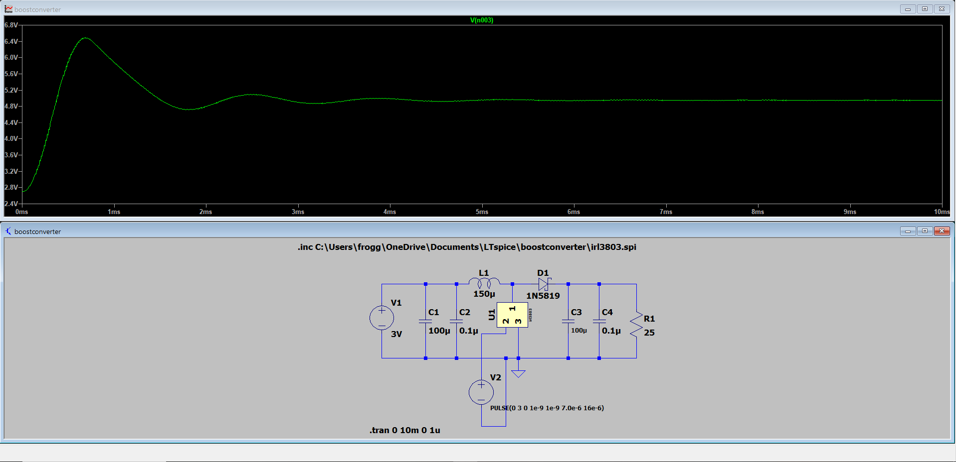
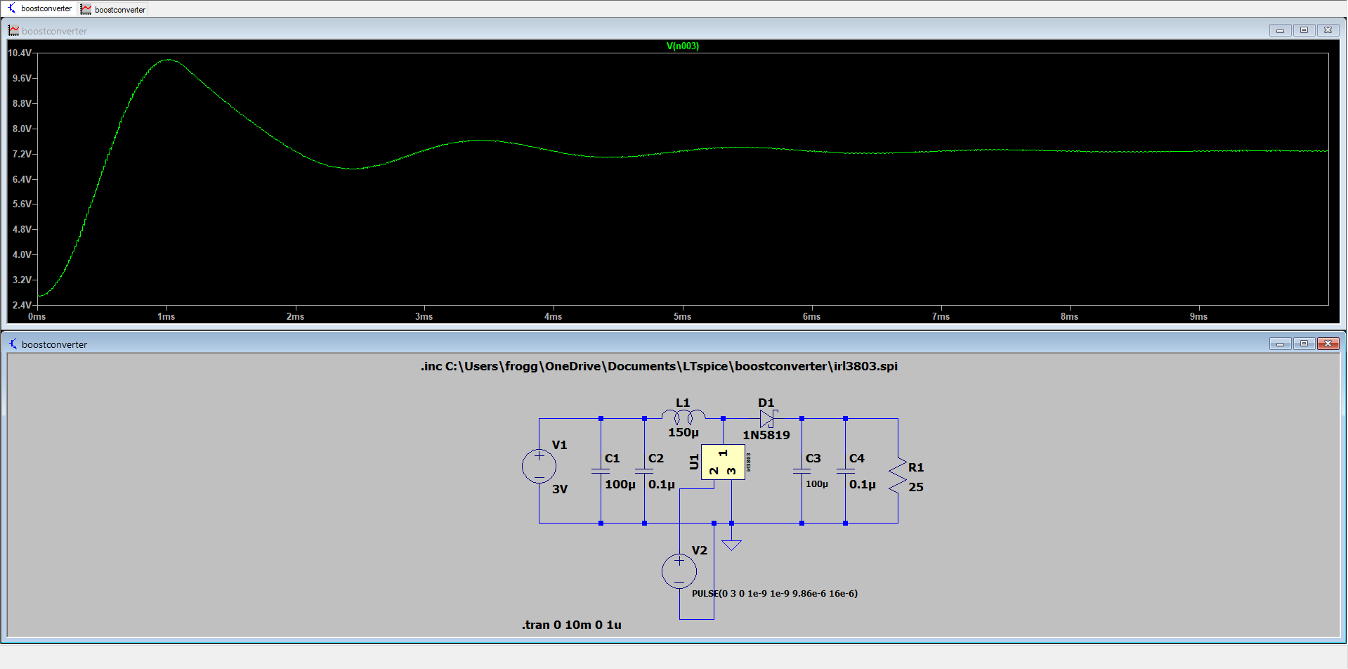
I am new to electrical engineering and am building a boost converter project, which takes 2.4-3 V input to 5 V output. I simulated my results in LTspice to check if it works. My hand calculated duty cycle of 0.616, considering 80% efficiency, results in around 7.2-7.3 V. After playing around with the simulator, I found that a duty cycle of 0.4375 yields approximately 5 V. The inputs are two AA alkaline batteries in series, since min and max voltage is 1.2/1.5 V each then Vin(min) is 2.4 V and Vin(max) is 3 V: the equation I used to calculate the duty cycle used Vin(min), found from TI's website: https://www.ti.com/lit/an/slva372d/slva372d.pdf?ts=1729356262259
QUESTION:
Why are the results different? Which value of duty cycle will give me the closest real-life approximation? I understand that LTspice probably doesn't incorporate efficiency but I don't want to blow anything up after I assemble the circuit in real life (the output will go to a USB-A port converter, which takes a 5 V input). Screenshots of my simulation are shown below; the first is trial and error duty cycle (~5 V), the second is with hand calculated duty cycle (~7.4 V).


.stepthis value upward to get a rough estimation of what happens as your battery drains. You should also see what happens if you change your load resistor from 25ohm to 2.5kohm. All converters like these are meant to be used with a control loop to regulate the output. \$\endgroup\$