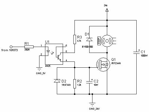
It's getting very hot because your PWM frequency is way, way to high, and you have a low-pass capacitor on the gate, for some reason.
Basically, for PWM to work properly, the FET needs to be entirely on, or entirely off the great majority of the time.
With the circuit you have, your PWM signal is being converted to an analog voltage by R3, R4, and C2. This is then partially biasing the gate on, which basically turns the FET into a voltage-controlled resistor. The resistance of the FET is then causing it to dissipate a lot of power.
You need to drop your PWM frequency massively (is it really 244 Khz?). Generally, the 500-15000 Hz ranges work well, though it can cause the motor to emit audible noise due to magnetostriction.
Then, you need to entirely get rid of C2 and significantly reduce the value of R3.
Basically, you want the waveform on the gate of the FET to be either 15V (the zener voltage of D2) or 0V 99+% of the time. Remember, the FET will only dissipate significant energy when the gate voltage is between ~2-4V (the gate threshold voltage) and ~10V (at which point the FET is entirely biased on.
The maximum reasonable PWM frequency can be calculated using the turn-on and turn-off resistances (R2, R3) and the FET gate capacitance (which for the IRFZ44 is roughly 1470 pF). This resistance and capacitance form a RC filter which dictates the minimum switching time of the circuit.
From that, you can calculate the time spent between \$V_{g_{th}}\$ (the "FET begins to turn on", or "threshold" voltage), and the \$V_{g_{sat}}\$ (the gate saturation voltage, which is when the FET is completely on). You then take this time, and use a PWM period where the ratio of the switching time to the entire PWM cycle is very large (e.g. \$\frac{T_{switch}}{T_{pwmCycle}} < 0.01-0.05\$)

