1
\$\begingroup\$

I’m designing a PCB powered by a 3-cell LiPo battery. The battery provides +12V, which is stepped down to +5V using a buck converter. From there, the +5V is further stepped down to +3.3V using an LDO regulator. Both +5V and +3.3V are needed in the design, which is why I step the voltage down in this manner.

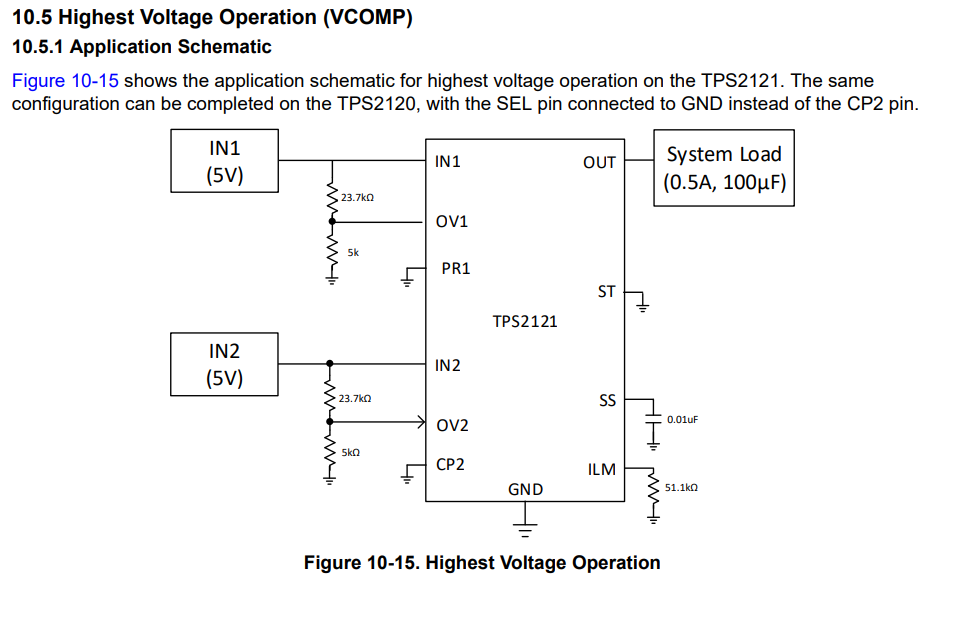
To simplify powering the circuit for programming the MCU, I’d also like to allow the circuit to be powered via USB (Type-C) without relying on the battery. I decided to use the TPS2121 power switch to manage the input power, so I can connect either the battery or the USB. Since both inputs are +5V, I followed the example schematic provided in section 10.5 Highest Voltage Operation (VCOMP) of the TPS2121 datasheet. This configuration is suitable since the current output matches my requirement (0.5A).

My Questions:

1) Hotplugging and Voltage Spikes:

If the TPS2121’s inputs are powered by the +5V from the buck converter and +5V from the USB Type-C, do I need to place a TVS diode at the input of the power switch for protection against voltage spikes during hotplugging(10.7 Hotplugging with TPS212x)? Considering that the PCB traces for the buck converter are short, and the USB cable length is under 1 meter, is there still a possibility of significant voltage spikes when hotplugging the USB?

2) Capacitor ESR:

Under section 11 Power Supply Recommendations of the datasheet, it mentions using low ESR ceramic capacitors with X5R or X7R dielectrics. What qualifies as "low ESR" in this case? Are all ceramic capacitors sufficient for this purpose, or are there specific ESR values I should aim for?

3) Schematic and Output Capacitor:

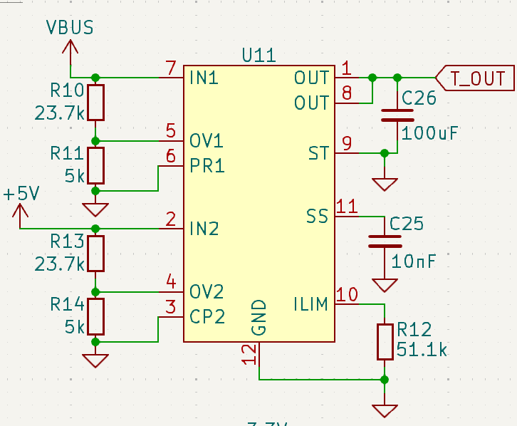
Did I correctly follow the recommended schematic? The datasheet schematic shows only one OUT pin, but based on the layout provided, I assumed the two OUT pins need to be connected together. Is this correct? Regarding the note about the system load (0.5A, 100µF) in the example, does this mean I should place a 100µF ceramic capacitor at the OUT pins to stabilize the output?

The schematic from the datasheet:

enter image description here

My schematic of the TPS2121:

enter image description here

The whole power schematic:

enter image description here

\$\endgroup\$
1
  • \$\begingroup\$ What you plan sounds similar to the classical Arduino Uno. You could check its (public) schematics for some hints. \$\endgroup\$
    – tobalt
    Commented Nov 24 at 19:51

1 Answer 1

1
\$\begingroup\$
  1. Yes the datasheet explicitly warns about spikes when hotplugging like USB. Even one meter and shorter cables have inductance. It is best to put protection than to damage the device.

  2. There is no separate mention of ESR value, the intention is to say use low ESR ceramics and X5R and X7R capacitors are examples of low ERS capacitors.

  3. Yes the packages have more than one IN pin and OUT pin and pins with same name must be connected together. The 100uF is just an example of input capacitance of next system load. With USB as source, you have a hard limit of 10uF directly on USB connector side. This mux has adjustable slew limits so it may tolerate more capacitanve than 10uF total on input and output, if it soft switches the USB to system capacitance. I would not put 100uF load after the mux unless it is guaranteed that it does not exceed surge limits of USB specs.

\$\endgroup\$
2
  • \$\begingroup\$ Thank you for the explanation! Just to make sure that I understood correctly we cannot place a 100µF capacitor at the output of the TPS2121. Even though the capacitor is technically on the output of the IC, when the USB is plugged in, the capacitor would be directly connected to the USB line. This would violate the USB specification, as it could cause a high inrush current that exceeds the surge limits. \$\endgroup\$
    – Robert
    Commented Nov 24 at 20:49
  • \$\begingroup\$ Also, we don’t actually need a 100µF capacitor on the output of the IC in this design. The 100µF mentioned in the datasheet example was only there to represent the input capacitance of the next system load and isn’t a mandatory requirement for the circuit itself. Is my understanding correct? \$\endgroup\$
    – Robert
    Commented Nov 24 at 20:49

Your Answer

By clicking “Post Your Answer”, you agree to our terms of service and acknowledge you have read our privacy policy.

Not the answer you're looking for? Browse other questions tagged or ask your own question.