0
\$\begingroup\$

I am building a power PCB which will take in 48V (at a max of 10A) and convert it to 5V (using a buck converter) and 7.4V (using a separate buck converter.) I am adding in reverse polarity protection and overvoltage protection. The power supply I will be using to get the 48V can be found here. It's not relevant, but adding in case it helps you to give your advice.

My question is: Do I need a large capacitor on the input power train? I have tentatively selected a 470uF aluminum capacitor.

enter image description here

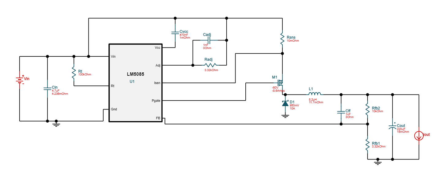
I would like to have a low ripple input power to the buck converters. However, the buck converters have their own (smaller) capacitors on their VDD pins. Are these smaller ones enough? Note that the 48V port goes directly into the buck converters. Here is the buck converter design. Vin would be the 48V from the input power train schematic above:

enter image description here

\$\endgroup\$
4
  • \$\begingroup\$ What's the current draw on that 48V rail? \$\endgroup\$ Commented Dec 23, 2021 at 19:33
  • \$\begingroup\$ Hi Jonathan. The max current draw will be 10A. I have just updated my question to include the 5V buck converter design. \$\endgroup\$ Commented Dec 23, 2021 at 19:35
  • \$\begingroup\$ M1 seems to be rated only 8.6A though - is that correct? \$\endgroup\$
    – Frog
    Commented Dec 23, 2021 at 19:43
  • \$\begingroup\$ Yes, that particular Buck will only have 8A Max through it. However, other components will draw current too so the input power train should be able to handle 10A. \$\endgroup\$ Commented Dec 23, 2021 at 19:53

1 Answer 1

1
\$\begingroup\$

You won't need a particularly large capacitor - the 48V rail comes from a regulated power supply so there's not much ripple to filter out anyway. However, you will need a low ESR capacitor there to filter out current spikes from the buck converter. Four 47µF aluminium polymer capacitors (each with ~30mOhms ESR) and a ~100nF X7R ceramic cap should do the trick. A 10A spike will then create a maximum ripple voltage of about 75mV (10A through 7.5mOhms of ESR, assuming not too much parasitic inductance).

The reason you need four parallel capacitors is that most typical 47µF 63V polymer caps can only take about 2.5A of ripple current; however, you have 10A of ripple. The ripple current rating is much more important in this application than the total capacitance.

Also, be careful with that PNP transistor (Q3). The base current from R4 is most likely not enough to allow 8A to pass through the transistor. You'll be lucky to get a current amplification of more than 20 out of a BJT at such high currents. Another P-channel MOSFET would be better suited.

\$\endgroup\$
2
  • \$\begingroup\$ Hi Johnathan, thanks very much for your advice. Just to clarify, when you say I will need 4 parallel capacitors (and another 100nF cap in parallel), do you mean in the first schematic? So replace the circled 470uF cap with the 5 in parallel? \$\endgroup\$ Commented Dec 23, 2021 at 22:29
  • \$\begingroup\$ Yes, exactly. Though, given that your buck converter already has a ceramic cap at its input, you most likely don't need yet another 100nF one. The four polymer caps should suffice. \$\endgroup\$ Commented Dec 23, 2021 at 23:05

Your Answer

By clicking “Post Your Answer”, you agree to our terms of service and acknowledge you have read our privacy policy.

Not the answer you're looking for? Browse other questions tagged or ask your own question.