3
\$\begingroup\$

I just attempted my first project with an LCD, and it did not go well. I am hoping to get some advice on how to prevent this from happening to my next LCD.

On the first night everything seemed to work fine - the LCD was bright and clear. On the 2nd night I suddenly noticed smoke coming from the backlight LED+ pin (pin 15). LED+ smoking
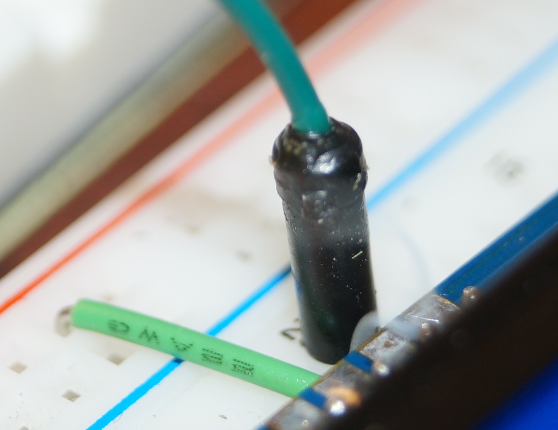
I measured the current going through the backlight and it was something like 80mA. Seems very high to me...

I examined the other side and could see melted plastic: Melted connector
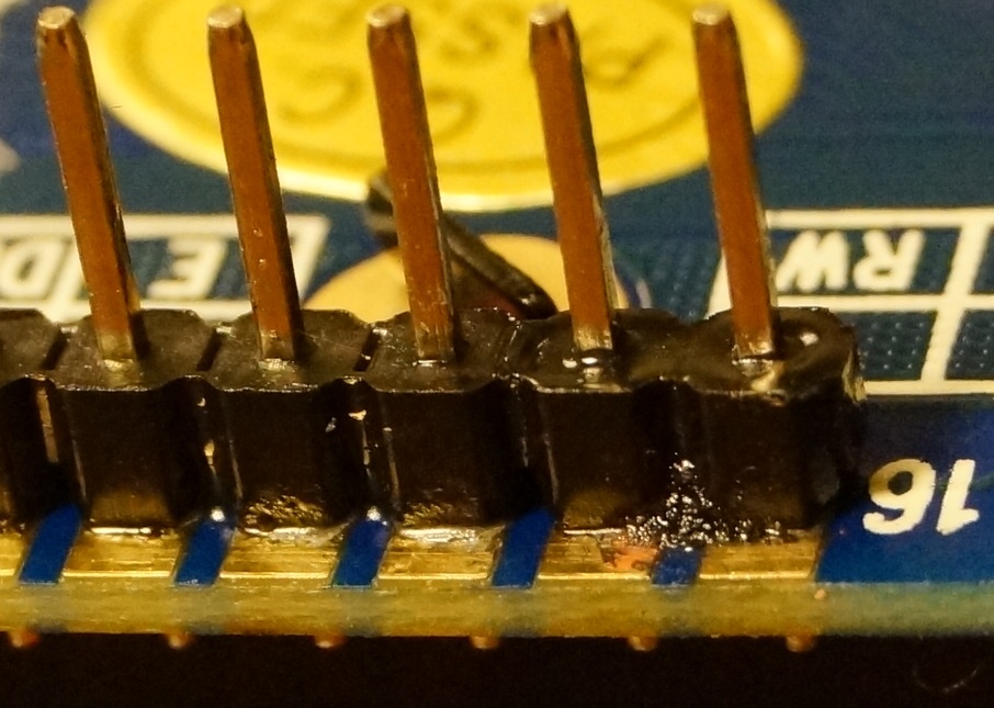
The datasheet says that no resistor is necessary for the backlight, but I tried hooking up a 12 ohm resistor anyways. This stopped the smoke, but caused the backlight to flicker. I found another datasheet for a similar LCD, and that one required 4.2V instead of 5V on the LED. I tried doing that as well by hooking up the LED through two diodes in series, but this setup continued to smoke. I measured the current again, and now it was drawing 600mA! I am currently running the LCD w/o the backlight, since it now starts making a boiling sound immediately when I connect it.

I have purchased this LCD here: http://www.adafruit.com/products/181 http://www.adafruit.com/datasheets/TC1602A-01T.pdf

And hooked up the backlight in accordance with this tutorial: http://learn.adafruit.com/character-lcds/wiring-a-character-lcd

Note that both the tutorial and the datasheet hook up the LED directly to +5V, which is exactly what I did.

So, what could have gone wrong? What precautions can I take to prevent this from happening again? Any suggestions would be appreciated!

Here is a video that shows a bit more of the setup and the smoke: http://www.youtube.com/watch?v=Wdqyi4hqlMw

Thank you!

\$\endgroup\$
10
  • \$\begingroup\$ It's entirely possible you simply have a defective backlight. Also, is that a 5.25" disk drive sound in the background of the video? :) \$\endgroup\$
    – JYelton
    Commented Sep 12, 2013 at 8:01
  • \$\begingroup\$ In the second case the 4.2V would be the forward voltage drop of the LEDs so rather than use diodes you should have say used an 8R2 resistor for 100mA of current. \$\endgroup\$
    – PeterJ
    Commented Sep 12, 2013 at 8:03
  • \$\begingroup\$ @JYelton: Ha-ha, no - the sound is the camera's lens motor. \$\endgroup\$
    – Val Blant
    Commented Sep 12, 2013 at 8:05
  • 3
    \$\begingroup\$ The data sheet clearly states :- NOTE: Do not connect +5V directly to the backlight terminals. This will ruin the backlight. \$\endgroup\$
    – MikeJ-UK
    Commented Sep 12, 2013 at 8:07
  • 3
    \$\begingroup\$ However, the datasheet TC1602A-01T.pdf does have an Interface Pin Functions table on the same page which says 5V for the LED+ signal. The datasheet is inconsistent. \$\endgroup\$ Commented Sep 12, 2013 at 8:09

2 Answers 2

4
\$\begingroup\$

The tutorial you followed says

On the vast majority of LCDs (including ones from Adafruit) the LCD includes a series resistor for the LED backlight.

If you happen to have one that does not include a resistor, you'll need to add one between 5V and pin 15. To calculate the value of the series resistor, look up the maximum backlight current and the typical backlight voltage drop from the data sheet. Subtract the voltage drop from 5 volts, then divide by the maximum current, then round up to the next standard resistor value.

The datasheet says

LED BACKLIGHT CHARACTERISTICS

COLOR         Wavelength Operating         Spectral line half   Forward Current 
              λp(nm)     Voltage(±0.15V)   width Δλ(nm)         (mA) 
Yellow-green  --         4.1               --                   100

NOTE: Do not connect +5V directly to the backlight terminals. This will ruin the backlight.

\$\endgroup\$
2
\$\begingroup\$

Problem solved.

The datasheet is inconsistent. In table INTERFACE PIN FUNCTIONS it shows Pin 15 connecting to +5.0V, yet at the bottom of the page it says not to connect it directly to +5V, as it will ruin the backlight (as it did over a period of 2 evenings).

The tutorial from the supplier also shows the backlight connected to +5V directly, but this is WRONG.

On my next LCD I'll use a (5 - 4.1) / 0.1A = 9 ohm resistor

\$\endgroup\$
1
  • 2
    \$\begingroup\$ The 100mA is probably the maximum allowed. It might be safer to use a 10 or even 12 ohm resistor \$\endgroup\$
    – pebbles
    Commented Sep 12, 2013 at 9:02

Your Answer

By clicking “Post Your Answer”, you agree to our terms of service and acknowledge you have read our privacy policy.

Not the answer you're looking for? Browse other questions tagged or ask your own question.