2
\$\begingroup\$

As preamble, this is the typical schematic for an opamp constant-current load used for testing power supplies and what not. (Sorry for the terrible circuitlab MOSFET symbol; that's an N-enhancement FET)
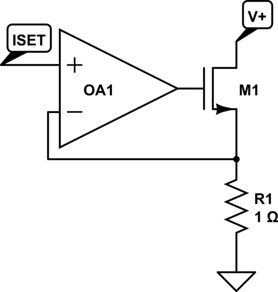
schematic

simulate this circuit – Schematic created using CircuitLab

I want to repurpose this standard design for use as a current-limiting stage for a linear regulator, like so. OA1 is a standard opamp, OA2 is a current-sense/instrumentation amp or something like that.
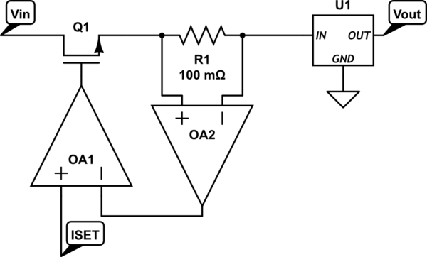
schematic

simulate this circuit

But I realized that this design uses a high-side N-channel MOSFET, so I need the opamp supply voltage to be higher than Vin to drive the transistor properly. I could switch to a BJT, but then I get a Vcesat drop across Q1 if the supply is not in current limiting mode. (ie suppose the LDO is drawing 800mA and the current limiting stage is set for 1A. OA1 will drive Q1 as hard as possible because it's not in current-limiting mode. If Q1 is a MOSFET, then you only get a small resistive drop, but if Q1 is a BJT, you get a diode-like saturation voltage drop.)

How should I alter the constant-current stage to solve this problem? eg powering OA1 from a boosted supply via a charge pump? Would a P-channel enhancement MOSFET work better in this scenario? Or will I have to use a BJT to get the job done?

\$\endgroup\$
2
  • \$\begingroup\$ Why not a P-MOSFET and flip the comparator? \$\endgroup\$ Commented Sep 18, 2013 at 3:01
  • \$\begingroup\$ I was thinking about a Pmos, not sure what you mean by "flip the comparator" though. There aren't any comparators in my diagram (OA1 is following the differential voltage across the sense resistor; OA2 is actually a differential amplifier but circuitlab didn't have a symbol for that). Could you show me a diagram of what you mean? \$\endgroup\$
    – tummychow
    Commented Sep 18, 2013 at 3:06

1 Answer 1

3
\$\begingroup\$

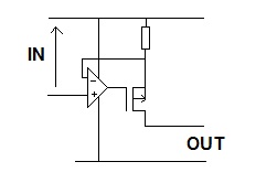
Why don't you just invert your top diagram so it uses a P channel FET: -

enter image description here

This will mean a little modification to the current demand input - it has to be positive supply referenced.

\$\endgroup\$
4
  • \$\begingroup\$ For a second I didn't know what you meant by "positive supply referenced" - it looks like you moved the sense resistor above the transistor in your diagram. Would it be possible to put a differential amplifier across the sense resistor and use that to drive the inverting input, as I did in my original diagram? Still works as intended? One other thing: I can turn the PMOS fully off (ie current limit of 0A) as long as the opamp's output can hit Vin, right? \$\endgroup\$
    – tummychow
    Commented Sep 18, 2013 at 12:41
  • 1
    \$\begingroup\$ @tummychow I see no advantage in using the current sense amplifier. It could also create stability problems too (ditto your original idea). Op-amps are designed to be close to the verge of stability at high frequencies and adding more silicon in the feedback loop is likely to cause sustained oscillations. Been here before!! You can turn the PFET off pretty much completely and if you have any worries about this, you can drive the PFET via a resistor from the op-amp and have another PFET there to clamp the gate drive to the positive rail. Be sure the op-amp has rail/rail i/p & o/p swing. \$\endgroup\$
    – Andy aka
    Commented Sep 18, 2013 at 12:57
  • \$\begingroup\$ Thanks for the clarification. The reason I wanted to use the differential amplifier was because Vin also varies. I'm designing a two-stage adjustable power supply with a switching regulator that feeds a linear regulator. The output of the switcher varies to match the dropout of the LDO (LTC3600 datasheet last page), and the current-limiting stage goes between them, so both sides of the current-sense resistor could shift up or down during normal operation. I'll fork that off into another question if I have to investigate it more seriously. \$\endgroup\$
    – tummychow
    Commented Sep 18, 2013 at 13:49
  • \$\begingroup\$ @tummychow Did you ever solve the problem with differential amplifier across the current sense resistor? I have a similar problem now where I need to limit current to a load, but the voltage supply can be either of 2 sources, and one is a battery that might vary between some values. \$\endgroup\$ Commented Dec 9, 2016 at 5:43

Your Answer

By clicking “Post Your Answer”, you agree to our terms of service and acknowledge you have read our privacy policy.

Not the answer you're looking for? Browse other questions tagged or ask your own question.