3
\$\begingroup\$

Having discovered just how awful the AC ripple is on some of my 5VDC wall-adaptors, I decided to make an Arduino program to calculate the RMS AC component and DC component of an adaptor under varying current loads.

My current issue is that the Arduino (and it's ADC's and DAC's) run on 5V, so 0-5V is it's analog input and output range. Many "5V" adaptors output a little more than that (and I want to be able to test 9V and 12V adaptors as well). So, I want a way for the Arduino to attenuate the input down to something within the 0-5V range, and the only way I can think of to do this is to use the Arduino's analog voltage output (which, I realize, is just PWM digital). Hence, I need a voltage-controlled attenuator.

The application requirements are:

  1. It must be able to attenuate the input anywhere from a gain of 1 down to a gain of about 0.25 (to get, say, a 15V input well within the 0-5V ADC range)
  2. The range of controlling voltages must also be within 0-5V. Furthermore, the range cannot be too small, since the Arduino can only select 256 values between 0-5V. In other words, I can't have a controlling voltage of 2.000V give me a gain of 1 and a controlling voltage of 2.001V give me a gain of 0.25, as the Arduino doesn't have that kind of control over its analog output.
  3. Any attenuation needs to affect the AC and DC portions equally, or else my ac_component/dc_component ratios will be erroneous.
  4. I would very much like not having to supply additional voltage rails. For example, I don't want to have to supply a +12V and -12V for a certain op-amp. If it can all be done with a 5V rail, that's optimal. Or, +12V will probably also be fine.
  5. Attenuation does not need to be linear with voltage. All I'm after is being able to calculate (RMS ac_component / dc_component), and those ratios will stay the same without my knowing the exact attentuation.
  6. I understand that JFETs (see the schematics below) aren't all that well-suited to DC operation for thermal issues or something. Gradual drift in the attenuation is okay. My Arduino program only samples the voltages from the wall-adaptor for about 1/10 of a second. As long as the gain doesn't change appreciably over that time span, things are fine.

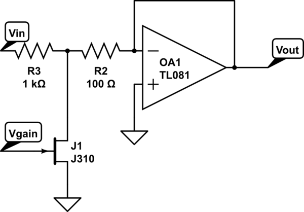
The first thing I tried was this sample which I found. It kinda did what I wanted, but it's inverting, so the output ends up being negative (and out of the 0-5V range of the Arduino).
schematic

simulate this circuit – Schematic created using CircuitLab

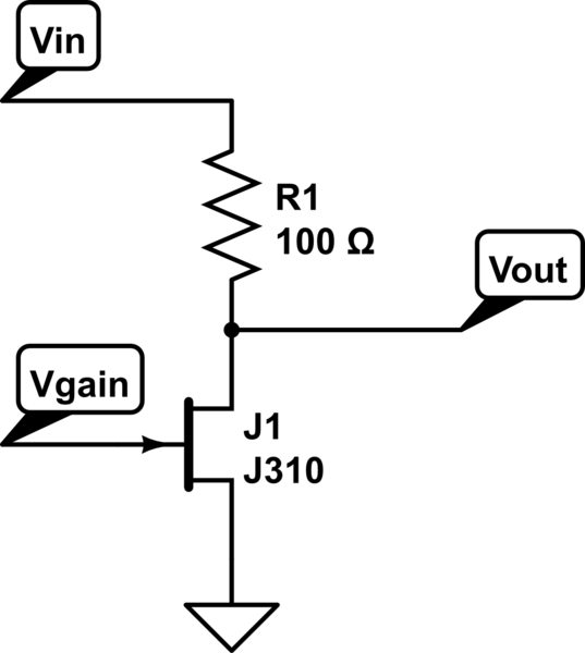
Then, I realized that the op-amp was probably just lowering the output impedance of the what's really just a voltage-divider with a JFET in place of one of the resistors, and I didn't need that because the Arduino has a much higher input impedance than the power-supplies I'll be testing, so I tried this ...
schematic

simulate this circuit

but I'm getting something strange. It looks like the AC component is getting affected by the gain-control input voltage, but not the DC component (see requirement 3). I clearly don't understand FETs like I should. Can someone either suggest some fixes to this approach, or suggest an alternative?

\$\endgroup\$
2
  • \$\begingroup\$ There is no such thing as a simple voltage attenuator that is anything like as precise as you need. JFETs as you have shown need a negative gate control voltage w.r.t. the source pin FYI. \$\endgroup\$
    – Andy aka
    Commented Oct 4, 2013 at 21:11
  • \$\begingroup\$ For the AC measurements you can AC-couple the power rail into an ADC input without attenuation, with the ADC input biased to 2.5 volts. \$\endgroup\$ Commented Oct 4, 2013 at 21:43

3 Answers 3

2
\$\begingroup\$

You want to measure dc voltages up to say 15 volts and these might have 2 volts of ripple superimposed for a half guess. Your smallest dc voltage might be 3v and you think your measurement accuracy may be unduly affected at the low end, yes?

Don't worry about it - make your input suitable for top peaks of 20 volts and you'll find that with a ten bit ADC you'll be just fine. Ten bits means a resolution of 20 ish milli volts and with a smidgen of noise superimposed and several samples averaged you'll easily achieve decent accuracy. Taking two samples then averaging gives you an 11 bit number and this will be accurate to 11 bits with out of band ac noise on top.

Try looking up dithering - it's a well formulated technique that improves the resolution of 16 bit CD audio so that it sounds less grainy to the ear on quiet passages of music. You just need a little bit of out of band noise to make it work.

\$\endgroup\$
0
\$\begingroup\$

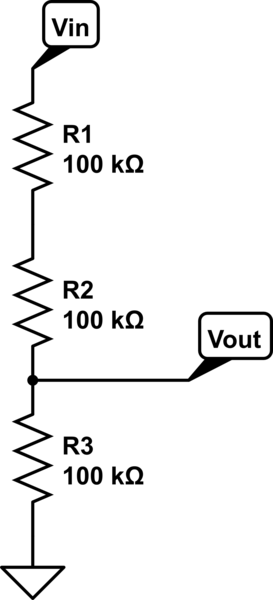
Your simplest solution is to simply use a resistor divider to scale a maximum voltage (12 V) down to say 4.5 V. i.e. a fixed attenuation. As Andy_aka points out you have a 10 bit ADC in there. This will be a linear scaling and if you are concerned about noise you can add or average the several samples. Make sure you don't load the inputs too much (so 100k's ohm). if you need precision then use multiple versions of the same resistor from the same batch (or buy matched resistors)

schematic

simulate this circuit – Schematic created using CircuitLab

The reasons you got a "strange" result on your JFET circuit (2nd picture) is that you made a common gate amplifier that has gain that is different for teh ac (small signal) component vs. the DC component of the signal.

\$\endgroup\$
1
  • \$\begingroup\$ Im not sure about arduinos but if it were a pic you'd need to buffer the input to the adc because the pic has a flaky feed through to the successive approximation logic and it needs a reasonably low impedance to drive into it. \$\endgroup\$
    – Andy aka
    Commented Oct 5, 2013 at 23:21
0
\$\begingroup\$

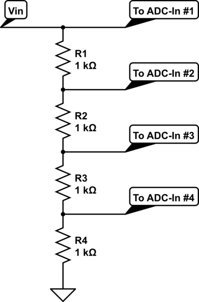
What I ended up going with is a little similar to rawbrawb's proposal of a voltage divider (and also what Andy aka hinted at). I'm going to use a voltage divider with multiple stages. Because the Arduino has a handful of analog inputs, I can just sample several divisions and then select the one which gives me the highest values without exceeding the Vref of the ADC...

schematic

simulate this circuit – Schematic created using CircuitLab

Also, from what I'm reading, the Arduino's ADC's can, at times, have input impedances as low as 10k, so I think I don't dare go much higher than 1k on the voltage divider stages. This shouldn't be much of an issue when I use this to test power supplies, as my current sink is going to draw up to 2A from 5V sources.

\$\endgroup\$
2
  • \$\begingroup\$ You're not going to use this for 9V and 12V supplies, right? If so, the ADC input #1 will probably die since you have no series resistance (input #2 might also die). When it dies, the power dissipated would probably destroy much of the rest of the chip. Perhaps I'm misunderstanding your idea... \$\endgroup\$
    – Justin
    Commented Oct 8, 2013 at 18:21
  • \$\begingroup\$ Oy! You're right. And using clamping diodes would mess up my DC-to-AC ratio. Looks like I'm back to rawbrawb and Andy's idea of just a fixed-voltage division. \$\endgroup\$
    – Jemenake
    Commented Oct 9, 2013 at 19:43

Your Answer

By clicking “Post Your Answer”, you agree to our terms of service and acknowledge you have read our privacy policy.

Not the answer you're looking for? Browse other questions tagged or ask your own question.