1
\$\begingroup\$

I have a PCB layout that I need to modify in order to protect the mosfet from a transient voltage when the user connects the power supply. Occasionally the mosfet gets damaged due to transient voltages. Will I be able to get away by just using a TVS diode connected from Source to Gate and without using a resistor on the Gate? The gate is directly connected to a via on the board and I cant mod it that easily.
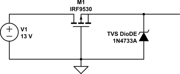
schematic

simulate this circuit – Schematic created using CircuitLab

\$\endgroup\$
2
  • \$\begingroup\$ The schematic in the question is somehow not very clear. It the gate really grounded? \$\endgroup\$
    – johnfound
    Commented Oct 19, 2013 at 5:42
  • \$\begingroup\$ @johnfound - Yep. This is a common configuration used to prevent damage on the application of reverse power. The mosfet acts as a ultra-low-drop diode in this application. \$\endgroup\$ Commented Jan 17, 2014 at 10:00

2 Answers 2

1
\$\begingroup\$

I am not sure that 1N4733 is fast enough to protect the MOSFET. I wasn't able to find any figures regarding it's speed - so it's probably not tested nor controlled. These transients are in nanosecond range - and it's really hard to do anything with them, other than have a resistor in series.

One possibility in current circuit to keep MOSFET safer without resistor is to pick part with higher Vgs in the same package, it should be at least double source voltage without resistor : signal reflection doubles voltage, parasitic inductance can drive it even higher.

\$\endgroup\$
1
  • \$\begingroup\$ the 1N4733a is actually a zener I couldnt change it on the schematic. The mosfet im using is IRLML5203PBF. Vgs is +- 20V \$\endgroup\$
    – nikolas
    Commented Oct 19, 2013 at 2:21
0
\$\begingroup\$

You can dampen the transients of connecting up the power source by adding a large capacitor in parallel with the power input. A large capacitor on the input will counter-act the inductive spike you may get when connecting power -- especially connecting long leads. If you want belt and suspenders, add a 220 uF 50V aluminum electrolytic, a 47 uF 35V tantalum and a 10 uF 35V ceramic. (Although I'm totally just guessing here -- for real engineering, you need to make measurements and run the numbers.)

Additionally, a very fast TVS intended for ESD protection will quite possibly protect these devices. Just make sure you have sufficient leeway -- a TVS I'm currently using is for example rated for a 17V normal operating/standoff voltage, and have a max clamping voltage of 27V.

Aluminum electrolytic + TVS is supposed to be "good protection" from what I've learned.

\$\endgroup\$

Your Answer

By clicking “Post Your Answer”, you agree to our terms of service and acknowledge you have read our privacy policy.

Not the answer you're looking for? Browse other questions tagged or ask your own question.