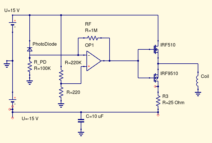
I'm building a magnetic levitation analog circuit. I realize there's a handful of ways to do this and I came up with my own idea ( which is partly why is doesn't work ... ) and would like to continue exploring this idea even if later it isn't as stable as other designs.
The setup is a IR LED and photodiode ( setup reverse bias ), that goes to an inverting amp ( IC OP07 what i had..), which then heads off to a push pull mosfet driver ( IRF 510 and IRF 9510 ).
My electro magnet is about 50 ohms wrapped around a pipe with ferrites in it. I added a lot of ferrite which I regret since the field doesn't change directions very fast.
I skipped the differentiator ( would like to try later ).
Power supplies are +15 and -15 VDC, with current limiting on the -15 since it's a wall wart. The positive supply, is good up to 10 A, it's a beast.
The gates are getting appropriate pos and neg voltages. And, with a pure resistive load ( 75 Ohm ) , the current drawn is what I'd expect. However, when the coil is connected, only the P channel mosfet draws current.
I'm wondering if the inductance of the coil is in causing this ?
UPDATE: I didn't include the IR LED in the diagram. It runs off the 15 V rail with a 1K. I have -0.03 V on my meter, when I check the ground. I have assumed this was from the photodiode. That's why I put the small ref volt on the OP1'a pos input.
On my meter, I do see a +15 to -15 V swing on the output of OP1, as I block and unblock the photodiode.
 Updated schematic fixed per gsills comments.
