2
\$\begingroup\$

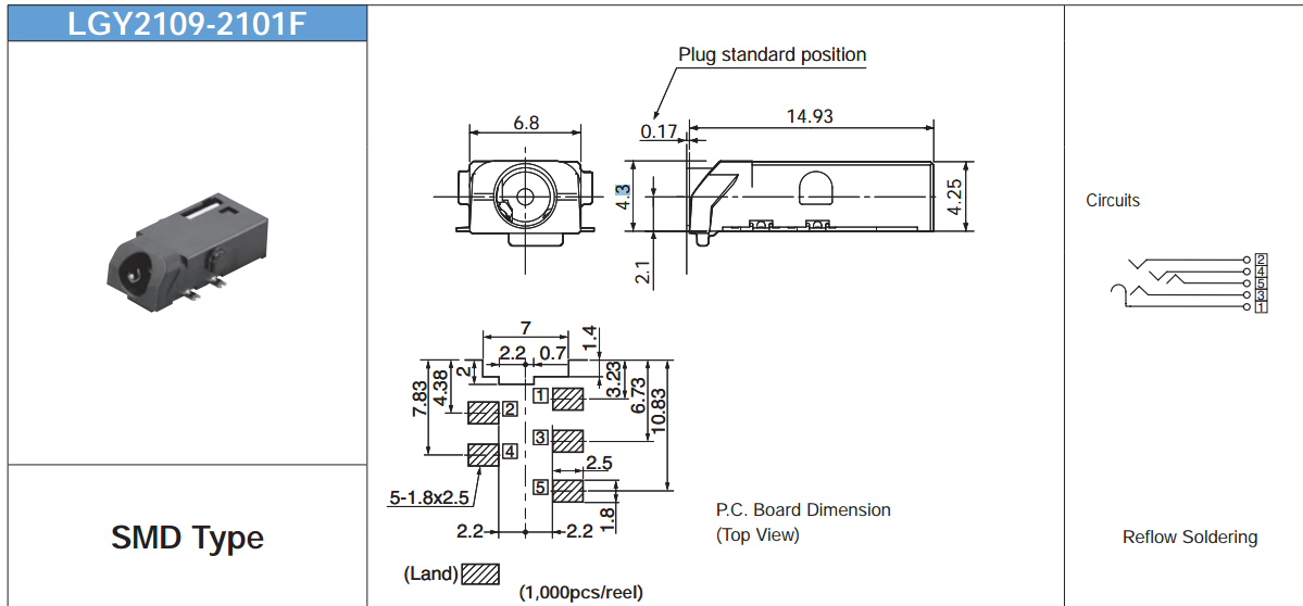
We are using this audio jack in our design. I am having trouble understand the schematic of this audio jack. My understanding is that

  1. Pin 5 and Pin 4 : Audio left and right
  2. Pin 2 or Pin 3 : Ground or Mic
  3. Pin 1: detect

Can anyone confirm my understanding? I think that the switch is normally open and pin 3 will short with pin 1 when the jack is inserted. Audio Jack
\$\endgroup\$
2
  • \$\begingroup\$ Unless you want us to say something about the drawing or the footprint, perhaps you could crop the other 4/5 of the image out so we can read the schematic symbol with ease. \$\endgroup\$
    – Samuel
    Commented Jan 16, 2014 at 7:28
  • \$\begingroup\$ @Samuel Right click, select View Image from the context menu (I'm assuming that you're using Firefox). You'll get a larger image. \$\endgroup\$ Commented Jan 16, 2014 at 7:41

2 Answers 2

2
\$\begingroup\$

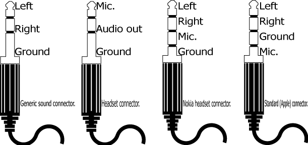
I always use this standard here, that its the same the Nokia and Apple use:

enter image description here

With this schematic, I think that maybe the pins 2 and 3 can be shorted when the jack is inserted.

\$\endgroup\$
0
\$\begingroup\$

My interpretation of the circuit symbol is

  • 1 = ground
  • 2,3,4 = tip contacts
  • 5 = switch, closed to 4 when NO plug is inserted

What the tip contacts are used for is not determined by the component but by convention and/or the exact device you want to use.

\$\endgroup\$

Your Answer

By clicking “Post Your Answer”, you agree to our terms of service and acknowledge you have read our privacy policy.

Not the answer you're looking for? Browse other questions tagged or ask your own question.