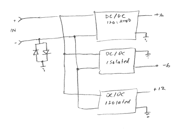
I inherited a power supply circuit design from another engineer, and he used a ground connection method I am not familiar with:

The input comes from an external isolated 48 V AC/DC power brick. The outputs supply several boards within a single enclosure.
My question is about the diode connection between the negative input terminal and the load-side ground.
The effects I see from this are
- Isolation provided by the DC/DC converters is negated.
- Negative input terminal will be held within about +/- 0.5 V of the load-side ground.
- Current might or might not be able to pass freely between the negative supply terminal and load-side ground, depending how the input common mode drifts relative to the circuit ground.
Some other notes about this system:
- The load-side ground is connected to chassis.
- Reverse-connection protection on the input is provided by other components not shown here.
- Several of these systems might be connected in parallel to the same 48 V source.
The question is, what was the design intent of adding the diode connection?.
