0
\$\begingroup\$

enter image description here

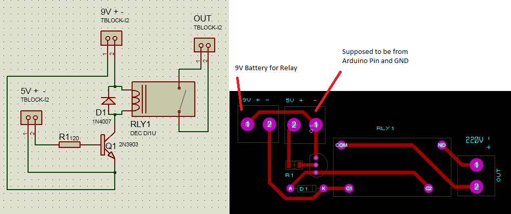
Done this in Proteus. I printed this out in the copper board and soldered components. But turns out my relay did not work.

I used a 9V battery in the the supposed to be 5 volts for the Arduino because I still don't have one. I have two separate batteries.

Put the power wire in the transistor base, connected transistor emitter to the GND did not switch my relay, doing it reverse switched my relay though and I don't understand why?

I'm not good in electronics that's why I'm trying out things. But why did my relay switch with the battery GND in transistor base and power in the emitter?

And my 470ohms resistor is not working I'm directly putting connection in the transistor base where it worked. I used a 2N2222 instead of a 2N3903, and a DEC DI1U relay. I used a tester to check if connection is good. My soldering is clean and I don't know what to do now.

My problem is that my resistor is not working, connection seems reversed and I'm a noob so big problem.

\$\endgroup\$
0

2 Answers 2

1
\$\begingroup\$

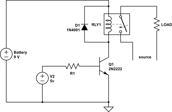
The correct connection is like

schematic

simulate this circuit – Schematic created using CircuitLab

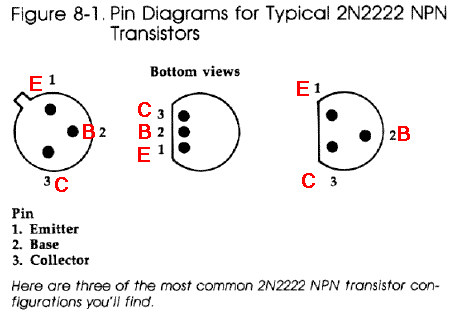
Also note that there are a few different pinouts for 2N2222, make sure that you have connected the transistor correctly depending on the case used.

enter image description here

\$\endgroup\$
12
  • \$\begingroup\$ I used multisim to simulate my circuit. ,nothing seems to be the problem. and its just the same isn't it? I just forgot to put the GND, but on pcb layout its just the output. \$\endgroup\$
    – yhunz_19
    Commented Feb 8, 2014 at 16:52
  • \$\begingroup\$ and I use the one in the middle. , \$\endgroup\$
    – yhunz_19
    Commented Feb 8, 2014 at 17:08
  • \$\begingroup\$ @aLzyAruManaois But in your schematic you show the + of 9v and + of 5v connected to the emitter, that is not what is shown in my schematic, how are they the same? The ground in not a problem, it can either be there or not. \$\endgroup\$
    – alexan_e
    Commented Feb 8, 2014 at 17:23
  • \$\begingroup\$ yes, but they're just terminal blocks. so in my pcb I just switch wire + to +, - to - .. i also turned my transistor so that the collector is to source and emitter is to ground., but when I apply power to the collector my relay won't switch, instead when I put the power in the emitter and GND in the collector it flicks. \$\endgroup\$
    – yhunz_19
    Commented Feb 8, 2014 at 17:50
  • 1
    \$\begingroup\$ Nice, so my 470Ohms will do then. I'll just look into my connections further and make sure. Thanks! \$\endgroup\$
    – yhunz_19
    Commented Feb 8, 2014 at 18:46
2
\$\begingroup\$
  1. Both low voltage connectors on your schematic are marked with reverse polarity.

  2. Try to keep 220V traces on PCB as far as you can from low voltage side. I suggest turning relay 90 degrees CW.

  3. You don't need to make traces of one width throughout your PCB. 220V traces could be made wider.

\$\endgroup\$
4
  • \$\begingroup\$ On the PCB 5V connector polarity marking is reversed again, though pin numbers correspond to schematic. So it's polarity marking is correct now :-) But 9V is still backwards. \$\endgroup\$
    – x4mer
    Commented Feb 8, 2014 at 13:10
  • \$\begingroup\$ but I put the wiring accordingly. and disregard the 5V terminal block because im directing it with a 9V battery and that's why im putting the positive in the GND and the GND to the suppose to be source of my transistor. \$\endgroup\$
    – yhunz_19
    Commented Feb 8, 2014 at 13:37
  • \$\begingroup\$ and how would it affect my pcb if high voltage where near low voltage sir? I thought it was far away enough. to keep my pcb small., \$\endgroup\$
    – yhunz_19
    Commented Feb 8, 2014 at 13:38
  • \$\begingroup\$ Rotating relay would not make your PCB bigger, but will make it a little bit safer. This is a general advice, related not to the issue we are discussing, but for amateur PCB routing in general. \$\endgroup\$
    – x4mer
    Commented Feb 8, 2014 at 15:43

Your Answer

By clicking “Post Your Answer”, you agree to our terms of service and acknowledge you have read our privacy policy.

Not the answer you're looking for? Browse other questions tagged or ask your own question.