0
\$\begingroup\$

I have a simple printed circuit board with simple circuit on it. Very beginner. No SMD.

As a part of this circuit I have transistor BC557.

If I don't solder the base pin of this transistor and test the circuit then transistor is closed (as expected) but when I solder it to a path on the board that has nothing else soldered to it (there were two resistors but I desoldered them) then the transistor is magically open now.

Transistor operates on voltages around 16V (on emitter) and on very small currents. The only load between collector and the mass are in parralel: 100k resistor and MOSFET gate-source.

Can printed circuit board be leaky in a way? Somehow allowing some current to flow from the base that's not connected to any other component?

Adding 1uF capacitor between base path and emitter path on PCB doesn't seem to help.

I noticed that if base is left unsoldered and I touch it with a screwdriver I'm touching with a finger then the transistor opens sometimes, even if I don't touch anything else in the circuit at the same time.

Can I somehow make it less sensitive?

This behavior didn't occur when I had same circuit powered by the same battery and tested with the same load but on breadboard.

The circuit I'm trying to build is that one: http://serwis.avt.pl/manuals/AVT746.pdf
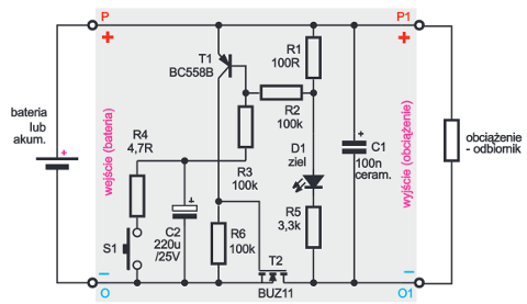
enter image description here

And it worked on lower voltages (less than 9V).

I tried putting 100k resistor between emitter and +16V but it doesn't seem to help either, transistor still is open when base is soldered to unconnected path (but it caused MOSFET to overheat, even though the sorce-drain current is just 2A).

I also swapped the transistor for another one (same) to rule out damaged element.

BTW This circuit cuts the battery power to the receiver on the right after a delay roughly controlled by C2. It turns it back on after pressing the switch. Cool thing about this one is that it can turn on an off large currents (in theory up to 30A) and work with voltages from 6 to 16V.

I replaced switch with transoptor (+480 Ohm resistor in series) so I can control this circuit with another one.

\$\endgroup\$
9
  • \$\begingroup\$ Got a schematic? \$\endgroup\$
    – EM Fields
    Commented May 18, 2015 at 17:21
  • \$\begingroup\$ What kind of solder are you using? Acid core (plumbing) solder will cause this kind of severe leakage. \$\endgroup\$ Commented May 18, 2015 at 17:48
  • \$\begingroup\$ Are you sure C2 is not leaking? What happens when you disconnect that from the original circuit? \$\endgroup\$
    – jippie
    Commented May 18, 2015 at 18:22
  • \$\begingroup\$ @SpehroPefhany Very old solder. Lead based with SW21 as flux. Wiki says it's weakly corrosive. It's water soluable. I think it's Ammonium chloride. This might be it as I made quite a mess. I rarely do anything with electronics and barely solder on. ;-) \$\endgroup\$
    – Kamil Szot
    Commented May 18, 2015 at 18:29
  • \$\begingroup\$ @jippie Yes. First thing I did in attempt to close the transistor was to desolder C2. On the breadboard disconnecting C2 causes transistor to close as it should. \$\endgroup\$
    – Kamil Szot
    Commented May 18, 2015 at 18:32

1 Answer 1

2
\$\begingroup\$

Could be leaky, could be pickup of AC hum from the mains or RF from AM radio etc. as the transistor will act as a detector.

To tell the difference, put a 1uF ceramic (low leakage) capacitor from base to emitter and see if the issue disappears.

In any case, you can reduce the sensitivity simply by connecting a relatively high-value resistor from emitter to base. Something in the range 10K-100K will likely work for you.

Edit: One thing that can cause a great deal of leakage is the use of acid-core (plumber's) solder. If this is accidentally used, clean the board with warm soap and water, preferably followed by isopropanol alcohol. I have seen mains circuits burn up as a result of this. As an aside, the solder used in plumbing was often 50:50 PbSn, so it would not solder as nicely (and will require much higher temperatures) compared to good electronic grade 63:37 solder.

\$\endgroup\$
5
  • \$\begingroup\$ I soldered 1uF ceramic (105J63) on the other side of pcb. It didn't help. Transistor is still open from the get go. \$\endgroup\$
    – Kamil Szot
    Commented May 18, 2015 at 16:58
  • \$\begingroup\$ Then it is leakage (or you missed a resistor!). Try measuring DC current from emitter to base. \$\endgroup\$ Commented May 18, 2015 at 17:16
  • \$\begingroup\$ A cure for leakage is putting a resistor right where you put that capacitor (emitter to base). \$\endgroup\$ Commented May 18, 2015 at 17:24
  • \$\begingroup\$ I won't be able to measure the current. My meter has damaged mA feature. \$\endgroup\$
    – Kamil Szot
    Commented May 18, 2015 at 17:29
  • \$\begingroup\$ I already have some resistors between base and emitter as a part of the circuit. I edited the question to add link to circuit. \$\endgroup\$
    – Kamil Szot
    Commented May 18, 2015 at 17:29

Your Answer

By clicking “Post Your Answer”, you agree to our terms of service and acknowledge you have read our privacy policy.

Not the answer you're looking for? Browse other questions tagged or ask your own question.