1
\$\begingroup\$

I have a bunch of LED Lamps from a yellow swedish furniture market. At that time they are connected with wireless power switches (Based on 433MHz). That is quite nice because I can control them from everywhere in my flat - but I can only SWITCH them. Want I really want to do is dim them.

I already found some Threads in the internet that say there are two types of that lamp. That one you can control and that one that already has a built in controller.

I dissambled one of mine but have no clue which one I have.

What is C1, U1 and U2? can I just attach the black and white wires to a transistor, that is fed with 4V using some LMxxx IC (or even connect 3 of them in a row an power them with 12V) and dim them using PWM that is generated by my Arduino?

This is the Head with the LED in the middle:
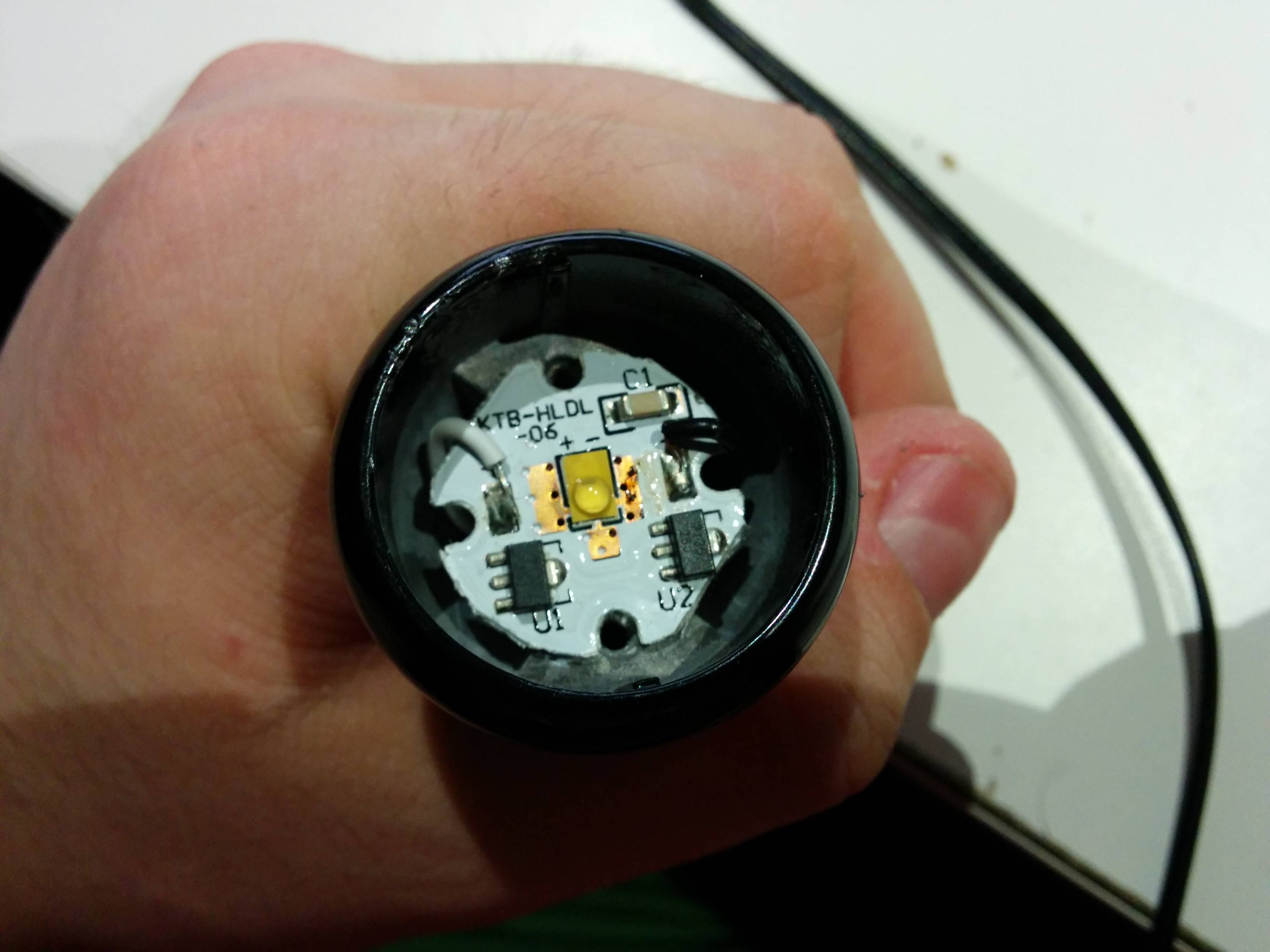
enter image description here

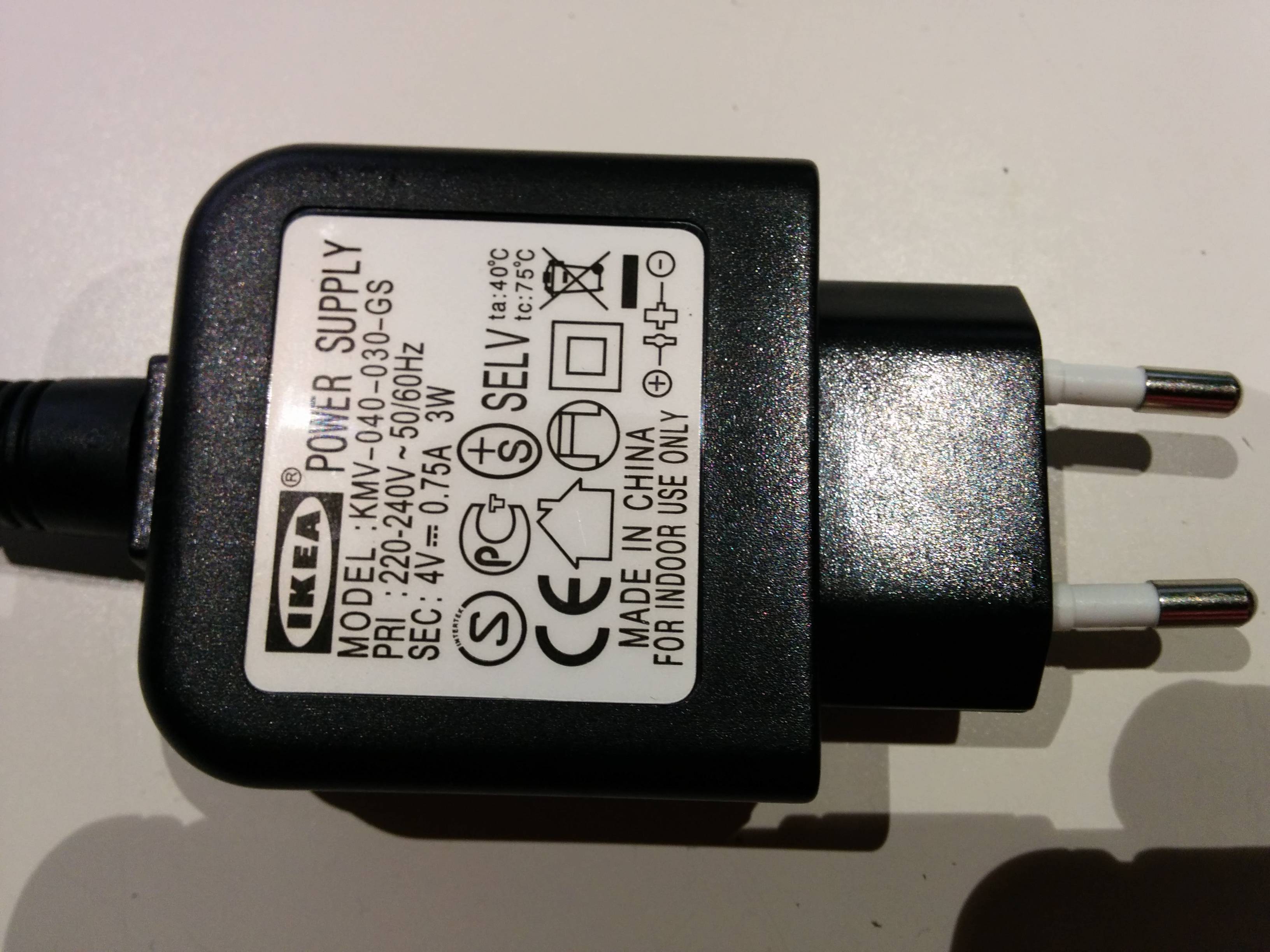
And this is the Power Source:

enter image description here

\$\endgroup\$
6
  • \$\begingroup\$ We're going to need the schematic as well as the markings on the ICs. \$\endgroup\$ Commented Mar 23, 2014 at 0:45
  • \$\begingroup\$ That's the problem. The LED Board is glued inside of the housing, I do not get it out without destroying it. \$\endgroup\$
    – Tobi
    Commented Mar 23, 2014 at 0:48
  • \$\begingroup\$ The continuity mode of your DMM is unlikely to damage the components. \$\endgroup\$ Commented Mar 23, 2014 at 0:52
  • \$\begingroup\$ Can you please rephrase your comment? I am not a native english speaker. What you you mean with DMM? \$\endgroup\$
    – Tobi
    Commented Mar 23, 2014 at 0:58
  • \$\begingroup\$ Digital multimeter. Don't use a basic continuity tester, e.g. a battery and a lightbulb, on circuits of unknown composition. \$\endgroup\$ Commented Mar 23, 2014 at 1:11

2 Answers 2

3
\$\begingroup\$

I've found 2 watt warm white LED with inbuilt current control at a supplier that appears idential and they give the following description:

What makes these interesting is that they have two AMC7135 250mA ICs in parallel to provide 500mA of current to the LED. Note that the regular AMC7135 provides 350mA, these appear to be a 250mA version and we have tested them and they do indeed feed the LED with a fixed 500mA in total. There's also a small chip capacitor onboard for proper operation of the ICs.

Looking at the AMC7135 Datasheet there doesn't appear to be a way to control the current output so it's largely a matter of if the device can start up and achieve regulation within a short enough period to use PWM. The datasheet doesn't seem to supply that information and doesn't give any hints to how the internal control circuit operates so it may just be a matter of trying it and if doesn't work you may have to replace the driver with a circuit suitable for PWM.

\$\endgroup\$
0
\$\begingroup\$

Just in case someone is still interested in PWM dimming the AMC7135 for LED luminaires, that is perfectly possible, but one cannot use any duty cycle. This explains it well.

\$\endgroup\$

Your Answer

By clicking “Post Your Answer”, you agree to our terms of service and acknowledge you have read our privacy policy.

Not the answer you're looking for? Browse other questions tagged or ask your own question.