2
\$\begingroup\$

For a small lab project I was asked to measure the propagation delay of a SN7400N NAND-Gate. In order to do this i connected one input pin to 5V and the other one to a clock running at 1 kHz. I connected an oscilloscope to the output and plotted it (top signal) together with the clock signal (bottom signal). As far as I know the delay is measured from 50% voltage to 50% voltage which would be about 1.5 squares, which is about 375 ns. This is far longer than the one in the specification (22ns).

Question: Where does this difference come from? Is it due to the input capacitance of the oscilloscope? Is it related to the frequency of the clock?
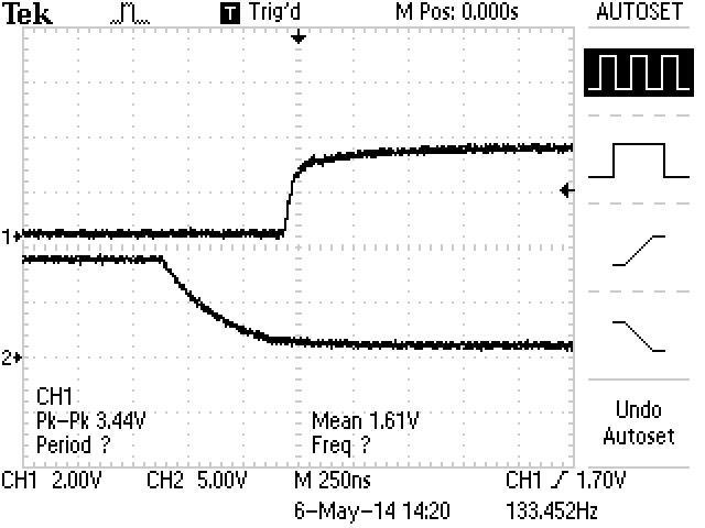
Propagation Delay

\$\endgroup\$
9
  • 3
    \$\begingroup\$ Measure the propagation delay on the other edge too. Also read the IC's datasheet re: logic levels : your 50% guess is wrong. \$\endgroup\$
    – user16324
    Commented May 21, 2014 at 19:27
  • 1
    \$\begingroup\$ It's a NAND gate, connecting one input pin to GND prevents the 1kHz from toggling the device! \$\endgroup\$
    – Andy aka
    Commented May 21, 2014 at 19:28
  • 1
    \$\begingroup\$ What Brian said ... In addition, you will get a more accurate reading if you can use an input signal with a much faster rise/fall time. \$\endgroup\$
    – Tut
    Commented May 21, 2014 at 19:30
  • \$\begingroup\$ @Tut: unfortunately I do not have another clock I could use. \$\endgroup\$ Commented May 21, 2014 at 19:39
  • \$\begingroup\$ If you connect 0 to an AND input you will always get zero out irrespective of the other input. The fact that it's a NAND just means you'll always get 1 out. It can't be clearer dude. What you describe in your comment is a NOR gate. \$\endgroup\$
    – Andy aka
    Commented May 21, 2014 at 19:40

1 Answer 1

5
\$\begingroup\$

Please see http://www.allaboutcircuits.com/vol_4/chpt_3/10.html for a discussion of TTL logic levels. A 7400 is not guaranteed to change state until the input drops below 0.8 volts. Given the long tail on your clock, I'd suggest that it is working just fine.

What I suggest you do is to use 2 7400's in series. The unused inputs should be pulled up to +5 with a 1k resistor, not tied directly. Then trigger your scope off the output of the first gate, and compare with the output of the second.

Oh yes, and you are WAY overdriving the input. Apply no more than 5 volts to a TTL input.

Finally, get into good habits, and tie the inputs of the unused gates either high or low. This is not usually a problem with 7400s - floating inputs will fairly reliably act as if they had a high input. Once you move on to other logic families, CMOS in particular, floating inputs will give you all sorts of grief. This particular bit of advice is not based on theoretical considerations. "Good judgment comes from experience. Experience comes from bad judgment."

\$\endgroup\$

Your Answer

By clicking “Post Your Answer”, you agree to our terms of service and acknowledge you have read our privacy policy.

Not the answer you're looking for? Browse other questions tagged or ask your own question.