0
\$\begingroup\$

I need to replace my 12VDC (bulb based) brake lights but I am unable to find a three-function light (Running/Brake/Off) with the same specs. I did however find a two-function light LED fixture (ON/OFF) with the exact same dimension.

Similar to these:
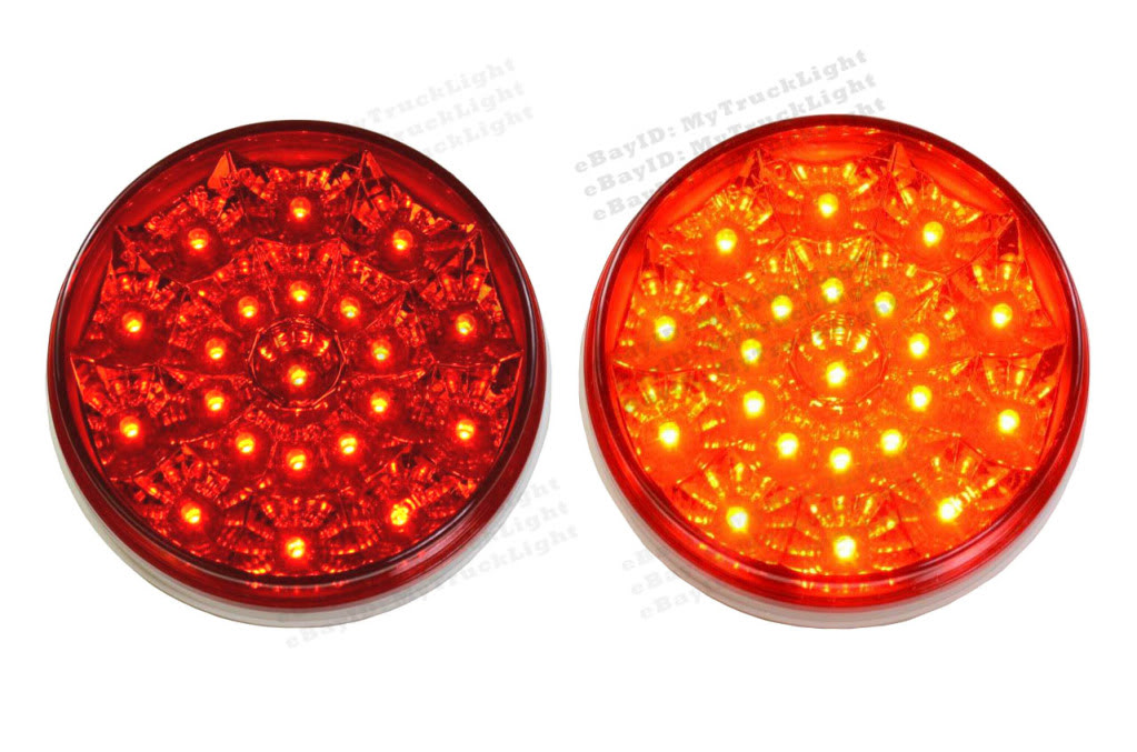
Brake Light Example

I want to install the two-function LED based light brake in my car but using it as a three-function light.

I thought of building a small circuit that gives the light fixture max 50% on each wire using a resistor and adding a potentiometer for configurable dimming.

So when the car is running the LED light gets max 6V via wire1, and when I brake, it get max 12V via both wire1 + wire2.

Does this approach make sense? Can you suggest anything else?

If it does, I have no idea how to build that circuit starting from my three wires, as simple as it sounds.

\$\endgroup\$

1 Answer 1

3
\$\begingroup\$

I am going to assume you currently have three wires going to your old brake light, ground, Running, and Brake:

Running    Brake    Lamp

   0         0       off
  12v        0       dim
   0        12v     bright
  12v       12v     bright

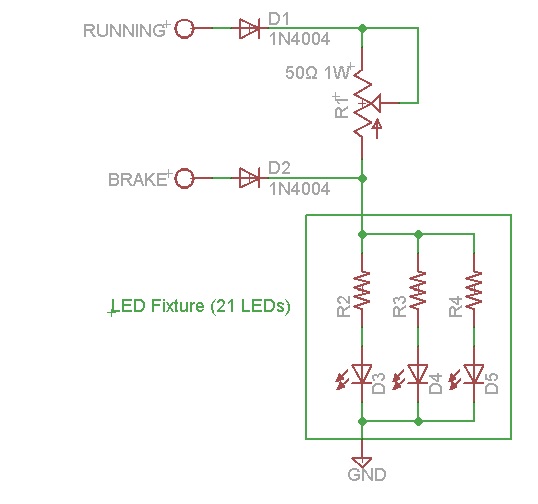
The following circuit should accomplish what you are looking for using one LED:

enter image description here

When neither RUNNING or BRAKE are on, the LED is off. When RUNNING is on, but BRAKE is off, 12v minus a diode drop for D1 goes through the pot R1 to reduce the voltage to the LED fixture. You'll probably end up with a value of only 10 to 20 Ω, but I suggest starting with a larger value pot just in case. Because of diode D2, there is no feedback into the BRAKE circuit.

When BRAKE is on, regardless of the condition of RUNNING, 12v minus a diode drop for D2 goes directly to the LED fixture. Because of diode D1, there is no feedback into the RUNNING circuit.

\$\endgroup\$
6
  • \$\begingroup\$ Sorry for not being specific. It is a LED sealed fixture (somthing like this i879.photobucket.com/albums/ab358/autonetsperformance/…) I bought off the shelf, so no specs on it whatsoever. \$\endgroup\$ Commented Jun 21, 2014 at 18:20
  • \$\begingroup\$ Sorry for being impolite btw; thanks for your help! I understand much better what I should do. I just need to find the proper resistance values. I will buy a 500ohn variable resistor this way I have more flexibility. \$\endgroup\$ Commented Jun 21, 2014 at 18:28
  • \$\begingroup\$ I did my calculations think you were talking about one LED, looking back I see you did say LED fixture, which I assume runs directly off of 12v. I'll revise my circuit. \$\endgroup\$
    – tcrosley
    Commented Jun 21, 2014 at 18:36
  • \$\begingroup\$ @tcrosley Most of these things seem to be <1A so 1N4004 or 1N5404 diodes should do the trick. \$\endgroup\$ Commented Jun 21, 2014 at 18:39
  • \$\begingroup\$ Thanks for your reply tcrosley. Two questions: 1. Is D2 really needed? I just thought of connecting the brake line straight to the fixture and it seems to work. 2. What is the section (the loop) on the right of R1? \$\endgroup\$ Commented Jun 24, 2014 at 20:51

Your Answer

By clicking “Post Your Answer”, you agree to our terms of service and acknowledge you have read our privacy policy.

Not the answer you're looking for? Browse other questions tagged or ask your own question.