0
\$\begingroup\$

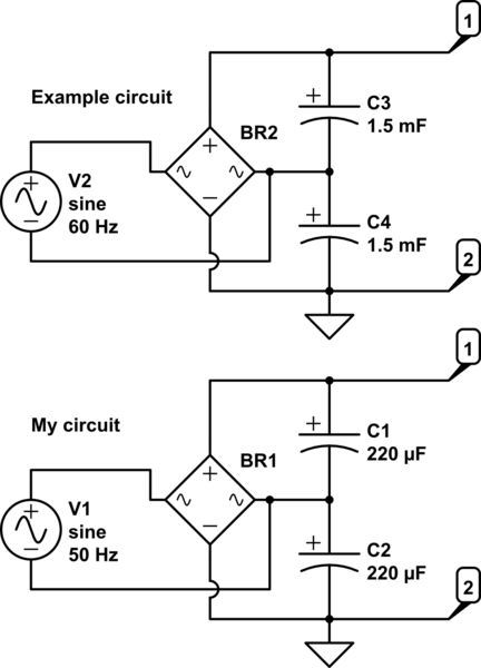
I'm testing a circuit for creating am unregulated "HV"DC source. The circuit is like this:
schematic

simulate this circuit – Schematic created using CircuitLab

The example I'm using uses a Variac with 120V. I'm limited to the mains supply in Europe of 230V. The description in the example uses 1500uF caps, I'm using 220uF caps since I don't have any higher.

Using the 120VAC of the transformer, the example circuit outputs 370VDC. Me, using 230VAC get 330VDC from my circuit between 1 and 2.

A couple of things are still unclear to me.

What is causing the difference between the outputs of both circuits? Is it merely the difference between capacitors? I would expect 240VDC and 500VDC respectively (minus some voltage drop) as output. Strangely, the polarity is also reversed as I expected. I would expect line 1 to be positive, 2 to be negative, but I have to use my meters positive probe on 2 and negative probe on 1 to read a positive voltage.

Secondly, is it required to connect the AC neutral between the caps? My knowledge of AC is limited and I'm trying to learn it, but although with AC the voltage is alternating, I would expect the neutral carrying the near-earth potential to be negative for cap 1 and positive for cap 2, and reversing this polarity to make the caps puff or in the worst case explode.

\$\endgroup\$
4
  • 1
    \$\begingroup\$ Have you built anything up to now? The schematics you posted can't be right, if ground is placed on terminal 2 when AC hot terminal goes negative you get a very high current in your bridge rectifier. \$\endgroup\$ Commented Jul 31, 2014 at 19:12
  • \$\begingroup\$ If you are trying to learn about AC, stop using mains power for your experiments. You are doing potentially lethal experiments with the set up you propose. \$\endgroup\$
    – jippie
    Commented Jul 31, 2014 at 19:23
  • \$\begingroup\$ About the reversal polarity my guess is that you have the probes swapped on the multimeter... I don't think these condy can survive such a high reverse voltage. \$\endgroup\$ Commented Jul 31, 2014 at 20:16
  • \$\begingroup\$ I've built it just to measure the result on 230V. The ground is the common indicator for the DC circuit, not an earth connection. I've checked the multimeter, but my negative (black) wire is connected to com, as it should. Jippi, would using a variac and lowering the voltage be safe enough? \$\endgroup\$
    – Sacha
    Commented Jul 31, 2014 at 20:44

2 Answers 2

0
\$\begingroup\$

If you don't connect the other AC wire between the capacitors, you will just have two caps in series being charged to around 325V through a full-wave rectifier bridge. But with the other AC wire connected between the caps, each cap gets the full 325V to itself during one half of the wave and will be effectively disconnected during the other half-wave.

To understand what's happening, draw the four diodes inside the bridge rectifier. Let's think of the midpoint between the caps as our ground reference - then the other AC wire will swing up to +325V and then down to -325V. When it swings up, current goes only through the upper capacitor and charges it, and the other cap just kind of dangles there thanks to the diodes preventing current flow. When the AC line swings down, only the lower cap gets charged. The output from both caps in series is double the input voltage peak.

Lower capacitance would only cause the output voltage to fall faster when there is a load connected. As for the wrong polarity, the only explanation is a wrong connection at some point. You can't always trust component markings, so check which way the diodes in the rectifier actually conduct!

For experimenting, I would suggest using the AC output from a small transformer, say 12V or so, and once you've seen it working correctly, only then connect it to 230V...

\$\endgroup\$
2
  • \$\begingroup\$ I've indeed switched to a lower voltage for testing. The markings on the rectifying bridge are correct though. What I can't always be sure of, is which of the two lines of the AC is the current line and which the earth. When I would finish the component and make it "plug and play", it can fail when the lines aren't connected according to the standards (here in house, they are reversed on different outlets. I'm looking a solution to make sure that the connection between both caps are always earthed. \$\endgroup\$
    – Sacha
    Commented Sep 21, 2014 at 21:41
  • \$\begingroup\$ In most countries, mains outlets are reversible and you can never trust which is neutral and which is live. AC circuits shouldn't need to know in any case. It may be safe to touch the neutral and to short it to the ground, but don't do that anyway (maybe a power company worker ends up swapping the wires, or something similar happens). If you really want to ground something, you need a transformer as a galvanic isolator. That way, on the secondary side any one point can be safely grounded. \$\endgroup\$
    – Rennex
    Commented Sep 23, 2014 at 0:24
0
\$\begingroup\$

Actually, I don't see anything wrong with your schematic (assuming that ground connection does not represent an actual connection to earth, and is just being used as an indicator for 'common' in your circuit).

You should be getting about 650VDC out of the doubler (230VAC in with no load other than a multimeter). As others have said, this is potentially lethal, as is the 230VAC mains, and you need to be taking appropriate precautions and using appropriately rated test equipment.

Your reversal of voltage sounds like a very serious problem, and I would expect that one or both capacitors will shortly be venting their smelly electrolyte if not actually exploding in your face. Check the bridge connections and capacitor polarities very carefully, and ensure that the capacitors have at least a 400VDC rating.

\$\endgroup\$
2
  • \$\begingroup\$ The ground does indeed represent common. It is the high power source a control circuit wil be switching. I guess maybe for learning using a transformator for a lower voltage might be safer. I've tried the circuit, carefully connecting earth ground and the polarity of the caps (rated 400VDC), but only received 330VDC between line 2 as positive and 1 as negative. I'm thinking about protection of "reversed polarity", but I can't think of anything since it's no way to be certain of the neutral when using different outlets. \$\endgroup\$
    – Sacha
    Commented Jul 31, 2014 at 20:35
  • \$\begingroup\$ I ofcourse missed the fact that 230V is RMS. This explains why I was expecting 240V for the example circuit instead of the 320V it produces. It still doesn't explain why I only measure 330V, but given the reversed DC polarity and the 330V with cap being so suspiciously close to the 325V peak, I guess I've been lucky having something not wired up correctly and only measuring one half of the wave. \$\endgroup\$
    – Sacha
    Commented Jul 31, 2014 at 23:16

Your Answer

By clicking “Post Your Answer”, you agree to our terms of service and acknowledge you have read our privacy policy.

Not the answer you're looking for? Browse other questions tagged or ask your own question.