0
\$\begingroup\$

I was reading Hack Into a Timer AC Socket and when I got to this paragraph:

The design firstly have a RC buck? (not sure how to call correctly in English) circuit to step down the voltage from 220V AC to 5V AC, a 0.33uf safety capacitor (yellow one) used here, accompanying with a 1M discharge resistor. And after these two there is another current limited big resistor to prevent pulse and shock.

I was curious - I didn't even realize you could change AC voltage levels without a transformer (or at least not cheaper than with a transformer).

I understand that a resistor will lower voltage for a given current, but I would have expected AC mains to be too much power for a cheap resistor. And I don't get what the capacitor does - even if it is helpful here to get smoother DC power, wouldn't it interfere with anything else on the same AC line?

WARNING - ALL PARTS OF THIS CIRCUIT SHOULD BE CONSIDERED TO BE AT AC MAINS POTENTIAL AT ALL TIMES.

Capacitor C1 MUST be an "X RATED" capacitor specified by its manufacturer
for "across mains" use. NB NOT 'Y' rated.
Examples of X & Y rated capacitors
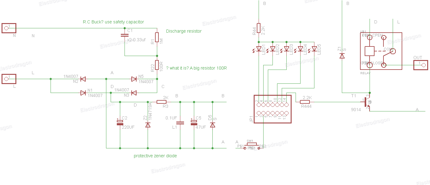
Schematic

\$\endgroup\$
6
  • 1
    \$\begingroup\$ Do you have a readable version of the schematic? Clicking the thumbnail in that article gets me a server error. \$\endgroup\$
    – gwideman
    Commented Aug 15, 2014 at 1:06
  • \$\begingroup\$ A resistor by itself does not "lower voltage". The concept you need to study is "voltage divider". en.wikipedia.org/wiki/Voltage_divider \$\endgroup\$
    – gwideman
    Commented Aug 15, 2014 at 1:08
  • \$\begingroup\$ Actually, I do - change the subdomain to WWW and the links work: electrodragon.com/wp-content/uploads/sites/7/2014/08/… \$\endgroup\$ Commented Aug 15, 2014 at 1:14
  • 1
    \$\begingroup\$ That looks somewhat like a very poorly laid out bridge rectifier with an input filter. \$\endgroup\$
    – sherrellbc
    Commented Aug 15, 2014 at 1:17
  • \$\begingroup\$ @RussellMcMahon Are there cases where a Y capacitor would be less safe than an X capacitor? \$\endgroup\$ Commented Aug 15, 2014 at 2:49

2 Answers 2

3
\$\begingroup\$

This is a capacitive dropper power supply. The bulk of the voltage is dropped across the 'safety' rated capacitor C1. It acts a bit like a resistor but does not dissipate significant heat. The reactance is Xc = \$\dfrac{1}{2\pi f C} \Omega\$.

R22 prevents an excessive surge if the plug gets put in at the peak voltage of the mains. R1 discharges C1 so you won't get a shock from the AC plug prongs.

The bridge rectifier and Z2 give you a lower voltage DC smoothed by C2, further smoothed by C5. I don't think the part number is correct on Z2 and D5 should probably be another zener.

\$\endgroup\$
2
\$\begingroup\$

The primary voltage dropping device in that circuit is actually the capacitor. At 50Hz the reactance of a 0.33uF capacitor is about 9650 Ohms, so at 220V it limits current to ~23mA. The advantage of using a capacitor rather than a resistor is that it doesn't dissipate any real power, so it stays cool.

The series resistor is necessary to limit peak current during any spikes or other higher frequency events that might occur on the mains, as the capacitor's reactance reduces as frequency increases.

\$\endgroup\$

Your Answer

By clicking “Post Your Answer”, you agree to our terms of service and acknowledge you have read our privacy policy.

Not the answer you're looking for? Browse other questions tagged or ask your own question.