1
\$\begingroup\$

I connected a green LED to pin 13 and digital GND on Arduino Uno R3. pinMode was set to OUTPUT and digitalwrite was set toHIGH. The LED glowed normally.

However connecting same LED to the 5V and GND burnt it out. How?

Did not pin 13 on HIGH also have voltage of +5V ?

\$\endgroup\$
1
  • \$\begingroup\$ Have you looked at the schematic yet? \$\endgroup\$ Commented Aug 18, 2014 at 18:12

3 Answers 3

9
\$\begingroup\$

The microcontroller at the heart of the Arduino can handle about 40 mA of current per pin. Connecting the LED (apparently without a current-limiting resistor) directly to 5V and ground will cause it to burn out, as it pulls more than its rated maximum current.

Pin 13 will also be 5V, but the current is being limited (not in a good way) by the microcontroller. The LED will try to pull more, but the microcontroller can't source it, so the LED doesn't burn out (as quickly). However, the microcontroller is not designed to be a current limiter, so connecting an LED directly to an output pin can cause damage over time. How much current the LED tries to pull, depends on the LED.

Most standard LEDs operate with about 20 mA, and can handle shorter durations of higher current.

You need to use a current-limiting resistor with your LED, regardless of whether you use a digital pin or connect it directly to Vcc.

\$\endgroup\$
1
  • 4
    \$\begingroup\$ Or in other words, the voltage on the output pin isn't actually 5V when the LED is attached, because the Arduino can't pull it up all the way with the LED attached. \$\endgroup\$ Commented Aug 19, 2014 at 3:20
1
\$\begingroup\$

The digital pins of the Arduino can only source 40mA, the 5V rail can source much more than that depending on supply.

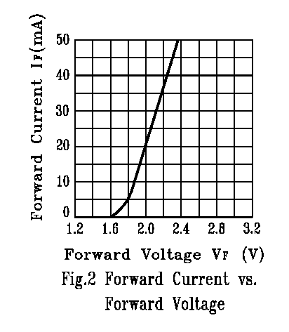
The LED blew up because you did not have a current limiting resistor. See here. When you attached 5V across the LED it likely tried to pull amps of current and instantly smoked. See this relationship. enter image description here

See how if you apply 5V, the current it would try to pull is exponentially higher than 40mA. The LED you used was likely rated for 20mA continuous. Poof

Additionally, if you put a voltmeter across the LED when connected to the digital output, you would not read 5V, likely around 2.2V if you used an LED with a similar curve to the generic one I posted. This is due to the arduino limiting the current to 40mA.

\$\endgroup\$
4
  • \$\begingroup\$ Extrapolating from that graph, it looks like it should be linearly higher, not exponentially. \$\endgroup\$ Commented Aug 19, 2014 at 3:20
  • \$\begingroup\$ @immibis: Your eyes are deceiving you, it's an exponential relationship \$\endgroup\$
    – Ben Voigt
    Commented Aug 19, 2014 at 3:31
  • \$\begingroup\$ It's possible the graphic was drawn by hand, or was pieced together on computer using a curve and a straight line intersecting at (1.8, 5), or similar. Sometimes it's quite obvious a graphic is not a computer generated plot of an exponential curve (or sinusoid etc) but rather whatever was expedient to create in a graphic design tool. The V-I relationship of the actual component should be exponential. \$\endgroup\$
    – Matt B.
    Commented Aug 19, 2014 at 5:01
  • \$\begingroup\$ I agree, the graph looks linear but should be exponential according to Shockley's equation. I just picked the first google hit. \$\endgroup\$
    – ACD
    Commented Aug 19, 2014 at 12:25
0
\$\begingroup\$

The Arduino output pins do not have hard, low resistance, switches to connect to +5V or ground - they use transistors which have a significant resistance which will limit the current the pin can deliver.

When you connect the LED across the power supply directly, the power supply will deliver as much current as it can in an attempt to maintain 5 volts - this will destroy an LED.

\$\endgroup\$

Your Answer

By clicking “Post Your Answer”, you agree to our terms of service and acknowledge you have read our privacy policy.

Not the answer you're looking for? Browse other questions tagged or ask your own question.