1
\$\begingroup\$

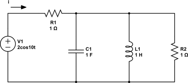
schematic

simulate this circuit – Schematic created using CircuitLab

Hi!

So I have a couple questions that I have already tried to solve that I think I am going in a little bit of the wrong direction with.

So at first I am suppose to find the source current \$i\$:

What I have tried to do seemed too simple. I made it so \$t=0\$. And so the voltage source was \$2\$ V. Then I did a KVL and got \$i = 1\$A. But I feel like I should've used impedances.

I know the impedances: Capacitor = \$-10j\$ Inductor = \$10j\$ Resistors = \$1\$

How do I find the complex power of each component with the impedences?

Also side noting:

How do I change \$2\cos(10t)\$ to Vrms?

Thank you :)

\$\endgroup\$

2 Answers 2

2
\$\begingroup\$

1) The total impedance of your circuit is

$$Z_{total}=R_1+(-j{{1}\over{10 C_1}}||j\cdot 10L_1||R_2)=R_1+{1 \over j\cdot (10C_1-{1 \over 10L_1})+{1 \over R_2} }=1+{1 \over 1+9.9j} \approx 1.01+j\cdot 0.0999 \Omega \approx 1.01504 \cdot e^{-j\cdot 0.098}\Omega$$

From that, you can easily calculate the complex amplitude of the current:

$$I={V_1 \over Z_{total}}={2\over1.01504 \cdot e^{-j\cdot 0.098}}\approx 1.97\cdot e^{j\cdot 0.098} A$$

2) The complex power through a resistor, capacitor or inductor can be expressed as \${V\cdot I^*} \over 2\$, where \$V\$ is the complex amplitude of the voltage across the element and \$I^*\$ is the conjugate of the complex amplitude of the current flowing through it.

  • The current of \$R_1\$ is the current calculated in 1). The voltage across it can be expressed as \$V_{R1}=I\cdot R_1=1.97\cdot e^{j\cdot 0.098}V\$. Therefore, \$S_{R1}={1.97\cdot e^{j\cdot 0.098}\cdot1.97\cdot e^{-j\cdot 0.098}\over2}={1.97^2\over 2}=1.94045VA\$. It is a resistor, so its power is purely real. (By the way, the ideal reactive elements – capacitors, inductors – have purely reactive power.)
  • Let the impedance of the 3 parallel elements be \$Z_2\$. The voltage across them is common, let's call it \$V_2=V_1\cdot {Z_2\over R_1+Z_2}={Z_2 \over Z_{total}}\$ (voltage division between \$R_1\$ and the parallel elements). I'm not going through the calculations, but every power can be now expressed as \${V_2\cdot I_{element}^* \over 2}={V_2^2 \over Z_{element}}\$.

3) Side note: The RMS value of a sine/cosine function is calculated as \$amplitude\over \sqrt 2\$, in our case it is \${2\over \sqrt2}=\sqrt 2 V\$.

\$\endgroup\$
3
  • \$\begingroup\$ I dont understand how you jumped to a conclusion in your impedance total. Where did the e^-0.098j come from? How did you transition the impedance to a numeric result like that? I got mine to equal the same as the answer below this.. Which is 10j/(10j-99). \$\endgroup\$
    – JT Hiquet
    Commented Sep 2, 2014 at 0:04
  • \$\begingroup\$ That is not the total impedance, only the impedance for the parallel RLC part. You still need to add the value of \$R_1\$, which is in series with them. \$\endgroup\$
    – hryghr
    Commented Sep 2, 2014 at 5:46
  • \$\begingroup\$ Regarding your question: complex numbers have several different interpretations, one being \$a+bj\$, where \$a\$ is the real and \$b\$ is the imaginary part. Another one is \$r\cdot e^{j\phi}\$, where \$r\$ is the amplitude and \$\phi\$ is the phase. (You can get the second parameters from the first ones like this: \$r=\sqrt{a^2+b^2}\$ and \$\phi=arctg({b\over a})\$.) The amplitude-phase representation helps calculate time-domain functions: \$i(t)=r\cdot cos(2\pi f t+\phi)=1.97\cdot cos(10t+0.098)\$. \$\endgroup\$
    – hryghr
    Commented Sep 2, 2014 at 5:56
2
\$\begingroup\$

To get complex power, you first need to get voltage on the three components after R1. You can calculate it like a voltage divider, when you first combine impedances of R2,C1,L1. \$Z_{L_1}=j\omega L_1=10j\Omega\$, \$Z_{C_1}=\frac{1}{j\omega C_1}=-0.1j\Omega\$, \$Z_{R_2}=1\Omega\$. Make inverse terms to get admittance, add them and invert again. \$Z_{R_2,C_1,L_1}=\frac{10j}{10j-99}\Omega\$. RMS voltage of source is \$\frac{2}{\sqrt{2}}\mathrm{V}\$, scaled by \$\dfrac{\frac{10j}{10j-99}}{\frac{10j}{10j-99}+1}\$ it is \$\frac{200\sqrt{2}}{10201}-\frac{990\sqrt{2}}{10201}i\, \mathrm{V}\$.

Now you can start with power calculation. \$S=V\cdot I^*=\frac{V\cdot V^*}{Z^*}\$, \$S_{L_1}=\frac{20}{10201}i\, \mathrm{VA}\$, \$S_{C_1}=-\frac{2000}{10201}i\, \mathrm{VA}\$, \$S_{R2}=\frac{200}{10201}\, \mathrm{VA}\$

Last thing is the power at R1. Voltage at it is \$\frac{2}{\sqrt{2}} \cdot \dfrac{1}{\frac{10j}{10j-99}+1}=\frac{10001\sqrt{2}}{10201}+\frac{990\sqrt{2}}{10201}i\, \mathrm{V}\$, and \$S_{R_1}=\frac{19802}{10201}\, \mathrm{VA}\$.

\$\endgroup\$
3
  • \$\begingroup\$ So i follow what you did until you did the power calculation. On SL1, how did you get -20/10201 i? and why is there an i? \$\endgroup\$
    – JT Hiquet
    Commented Sep 1, 2014 at 23:56
  • \$\begingroup\$ @JTHiquet Voltage is \$\frac{200\sqrt{2}}{10201}-\frac{990\sqrt{2}}{10201}i\$, its complex conjugate is \$\frac{200\sqrt{2}}{10201}+\frac{990\sqrt{2}}{10201}i\$. Their product is \$\frac{200}{10201}\$. And divided by \$10i\$ it is \$-\frac{20}{10201}\$. The i and negative sign denote it is inductive reactive power. To be exact, it probably should be marked \$\widehat{S_{L_1}}\$, like a phasor. \$\endgroup\$
    – venny
    Commented Sep 2, 2014 at 0:24
  • \$\begingroup\$ @JTHiquet Oops, I flipped a sign, inductive reactive power is positive, capacitive reactive power is negative. Answer updated. \$\endgroup\$
    – venny
    Commented Sep 2, 2014 at 9:03

Your Answer

By clicking “Post Your Answer”, you agree to our terms of service and acknowledge you have read our privacy policy.

Not the answer you're looking for? Browse other questions tagged or ask your own question.