2
\$\begingroup\$

So, here's the scenario:

I have an Arduino and an SD card. Unfortunately, I don't have one of the fancy shields, and I don't have the time to order one. As we know, Arduinos run on 5V, and SD cards run on 3.3V. I was thinking that I could use a series of voltage dividers to get the data going from the Arduino to the card (MOSI, Clock, SS) down to the correct voltage, but I'm not sure about putting together a step-up circuit.

Would I even need a step-up circuit for the MISO line, or could I just feed it directly into the Arduino? Does anyone have any ideas other than the ones I mentioned?

\$\endgroup\$
2
  • 2
    \$\begingroup\$ A resistor divider will not work for the VCC line. SD cards can draw up to 100 mA. \$\endgroup\$
    – Turbo J
    Commented Sep 16, 2014 at 14:44
  • 1
    \$\begingroup\$ @TurboJ, I Was never intending to use a divider for the VCC line. Arduinos have a dedicated 3.3V supply line, in case you were not aware. \$\endgroup\$
    – Tustique
    Commented Sep 17, 2014 at 20:00

2 Answers 2

1
\$\begingroup\$

If you do not have SPI clock running fast, and use the Arduino reference for setting the clock division for SPI peripheral to quite low (sub MHz would be good) you can definitely get away with simple voltage level shifting with resistors.

Do not worry about signals returning to the Arduino only being 3.3V, it will detect as logic HIGH (only just, but it works).

I have personally done this with an Arduino Uno and an SD Card breakout from Sparkfun. I used a breadboard and some resistors. Keep wires short of course.

This is the cheapest crapiest way you can do it, but honestly I do recommend some form of level shifter/translator, which with very little research you may find on the internet.

EDIT: If it helps, I used resistors less than 5K Ohm. I as those at Adafruit found out, 10K is too high. Specifically 1.8K and 3.6K

\$\endgroup\$
6
  • \$\begingroup\$ Thank you. I am planning to go back later and do it the correct way, but when you just need a simple data logger for something a few hours from now, things become far more hacky and cheap. We have resistors lying around, but I don't think that we just have a level shifter lying around anywhere. \$\endgroup\$
    – Tustique
    Commented Sep 16, 2014 at 14:14
  • \$\begingroup\$ @user38168 I added the resistor values I used, if that helps. Make sure your arduino's 3.3V output is used to power it. \$\endgroup\$
    – KyranF
    Commented Sep 16, 2014 at 14:18
  • \$\begingroup\$ Thanks for giving the resistor values as well. And just to confirm that it works, you did use the standard Arduino SD card libraries, right? \$\endgroup\$
    – Tustique
    Commented Sep 16, 2014 at 14:19
  • \$\begingroup\$ ATMega at 5V will probably accept 3.3V levels, but it does not have to. This SD specification guarantees minimum high output voltage of 0.75Vdd=2.475 V, whereas ATMega needs 0.6*Vdd=3 V. \$\endgroup\$
    – venny
    Commented Sep 16, 2014 at 14:28
  • 1
    \$\begingroup\$ @venny correct, but from my simple testing as long as it's supplied enough voltage and there is nothing weird happening, the IO is the full VCC level (3.3V) \$\endgroup\$
    – KyranF
    Commented Sep 16, 2014 at 14:31
2
\$\begingroup\$

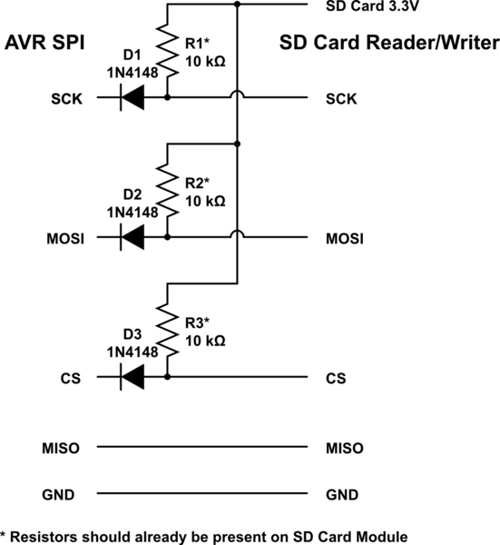
schematic

simulate this circuit – Schematic created using CircuitLab

Just use diodes to level shift between a 5V AVR and a 3.3V SD Card Reader/Writer. The 10K resistors should be on the SD Card Module but if they aren't, you'll have to add them.

\$\endgroup\$
1
  • \$\begingroup\$ No, not a good idea. The pullups provide substantially weaker drive than the series resistor example. \$\endgroup\$ Commented Nov 10, 2014 at 14:54

Your Answer

By clicking “Post Your Answer”, you agree to our terms of service and acknowledge you have read our privacy policy.

Not the answer you're looking for? Browse other questions tagged or ask your own question.