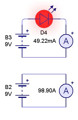
To answer the non-illustarted questions, as the LED current in the example picture is already answered (although, at 9Vdc it's also not constant, displayed is the starting current, it will peak somewhere above 100mA and drop off to 0 as the LED chip disintegrates).
Your first question: Do I need a resistor?
Probably yes.
You do not specify the buzzer's nature, if it is nearly purely resistive in its characteristic around 3VDC and has an approximate current of 15mA at 3VDC, then you might not need one.
Be aware with series connections, that the current through all devices is the same. If your buzzer is rated at 3VDC and 200mA, your LED will be "asked" to conduct 200mA as well, if you're lucky in that case it might just top off at 30mA at 2.5V, with a non-functioning buzzer.
If the buzzer is rated at about 3VDC and 15mA you should still add a 10 to 47 Ohm resistor (depending on the exact buzzer), to flatten the LED's response to slight variations in the buzzer's I/V characteristic.
Your second question: Why does current flow anyway? (Answer is gravely simplified, mind you)
A device is rated at 3V and a certain current. Let's say 10mA.
This rating means "If you give me 3V, I will take 10mA". Similarly the a signal LED (red, at least) is rated at 1.8V to 2.1V at 10mA. For a LED, because of its non-resistive behaviour is is safer to say "Give me 10mA and I will cause 2V", as voltage regulation on a LED is quite a dangerous thing to do, better to keep the current under control.
Now if you stack the LED and the 3V buzzer, which both have the 10mA specification, in a world where buzzers are well behaved resistive loads, you get a total that says "Give me 5V and I will take 10mA".

