voltage relation diodes of rectification process related to electronics
-
\$\begingroup\$ What have you already found in your research? This shows no evidence of effort, and reads like a homework question. Hence this is off-topic. Please read help center to understand the sort of questions accepted at ee.se. \$\endgroup\$– gbulmerCommented Sep 22, 2014 at 18:33
3 Answers
Here you can view the basic operation of a bridge rectifier.
1.why does ripple voltage increases by removing one of the diode from filtered bridge rectifier?
Removing a diode, transforms a bridge rectifier (so called full-wave rectifier) in a half-wave rectifier, i.e. get only a half-cycle rectified by each cycle of the signal to rectify. This reduces the amount of energy available per cycle. Viewed another way, increase the harmonic components of the rectified signal, resulting in a larger content of AC in the rectified output. The ripple factor is defined as
$$ RF = \dfrac{\sqrt{\sum\limits_{k=0}^{\infty}v_k^2}}{V_{DC}} $$
where \$v_k\$ is the amplitude of \$k\mathrm{-th}\$ harmonic.
2.why does ripple frequency becomes half when one of the diode is removed?
Suppose you have a line frequency of 60 Hz; with a full-wave rectifier, the output is a 120 Hz signal, since you have 2 pulses for each line cycle. Removing a diode, transform the rectifier in a half-wave, i.e. you have 1 pulse for each line cycle, then, a 60 Hz signal at the output.
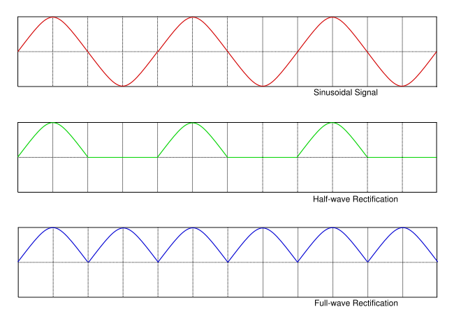
In the following images, you can see the differents rectified waves:

as you can see, half-wave (removing a diode) has the half number of pulses in the output than full-wave.
-
\$\begingroup\$ .Can you tell me what do you mean by harmonic component here? \$\endgroup\$– Ali AwanCommented Sep 22, 2014 at 18:16
-
\$\begingroup\$ The rectified signal is a periodic signal. It can be represented by a Fourier Series, i.e. by an infinite sum of sines and cosines. Each term represents a particular signal frequency, and the relationship is such that each frequency is an integer multiple of the fundamental frequency. For example, for 60 Hz, full-wave rectifier delivers a signal of 120 Hz (the fundamental frequency) and harmonics of 240 Hz, 480 Hz, etc ... The sum of all these components reconstructs the rectified signal. \$\endgroup\$ Commented Sep 22, 2014 at 18:23
-
\$\begingroup\$ @AliAwan I have append a link for a more detailed explanation on harmonics components. \$\endgroup\$ Commented Sep 22, 2014 at 18:26

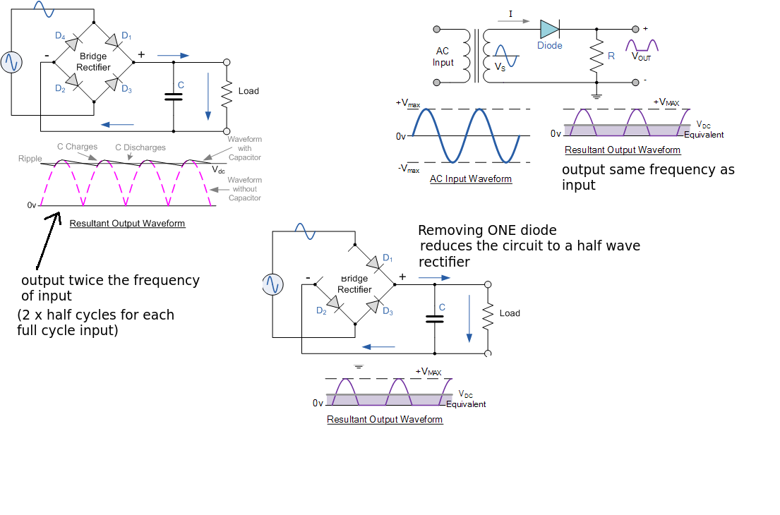
The bridge rectifier produces a full wave rectification. This means there is a current path through TWO diodes on each half cycle. The consequence is that the unsmoothed output would consist of DC + an alternating component at twice the input frequency. Adding a capacitor smooth out the AC but will leave a ripple voltage as it discharges between peaks.
Compare that with a half wave rectifier (single diode) circuit. For ONE HALF INPUT CYCLE there is no output. The capacitor has longer to discharge and so the amount of ripple will increase. Also the frequency of the AC component is the same as the input.
Now what happens if you remove ONE DIODE from the bridge rectifier circuit (see above). On one half cycle current will flow through D1, through the load and return through D2. On the next half cycle there is no return path for current through D3. This means no current can flow on this half cycle. The result is the circuit defaults to a half wave rectifier which increase the ripple and reduces the ripple frequency by half.
It doesn't matter which diode is removed as the diodes in a bridge work in diagonal pairs.
Assuming you are talking about a single phase rectifier here.
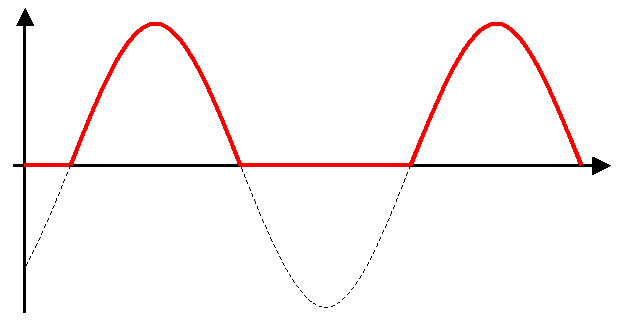
The removal of a single diode will essentially create a 1/2 wave rectifier.
The unfiltered voltage waveform appears as such:

