0
\$\begingroup\$

From one button press, I want to momentarily close two circuits with a small (< 1s) tuneable delay in between.

What term should I google for to find a schematic?

(For clarity, I want to press the normally-open momentary pushbutton once, which will close one circuit momentarily, then after a delay—the length of which is adjustable via a trimpot, for example, up to about 1s—momentarily close another circuit.)

\$\endgroup\$
7
  • \$\begingroup\$ The circuits I have in mind are 5-12V DC, to actuate a solenoid and turn on a spark gap generator. But in theory as suggested below you could turn on a relay and use that to switch anything. \$\endgroup\$ Commented Sep 23, 2014 at 16:52
  • \$\begingroup\$ Relays have their limitations, of course, but they are a very robust way of switching. My initial question/remark was aimed at "It may also be possible to use transistors or other ways, if the circuits are related". Cheapest is one R, one C and one Transistor per delay/circuit, but that doesn't work for all possible situations. \$\endgroup\$
    – Asmyldof
    Commented Sep 23, 2014 at 17:06
  • \$\begingroup\$ It sounds like what you want to do is close one circuit immediately with the closure of the pushbutton, then some time later - while the pushbutton is still closed - close another circuit, and then hold them both closed for as long as the pushbutton is held pressed. Is that right? Also, would you explain the purpose of the solenoid, please? \$\endgroup\$
    – EM Fields
    Commented Sep 23, 2014 at 17:18
  • \$\begingroup\$ Not quite, @EMFields—I've tried to clarify in an edit. The solenoid releases some flammable gas, the second activation is to put 5V across a spark gap generator in order to ignite said gas. It seems I need a little delay in order to let the gas mix with some air for maximum flammability. \$\endgroup\$ Commented Sep 23, 2014 at 19:50
  • \$\begingroup\$ @Robert Atkins: OK, but I'm still a little confused. Now it sounds like you want to fire a spud gun or something like that, and with a single button press - a "trigger",say - you want to initiate a cycle where the solenoid stays open for a time, dispenses some gas, then closes, then a delay ensues while the gas mixes with air and, finally, after the delay, the spark generator is actuated for a time, after which the cycle ends. I'm assuming that you want to generate a single cycle each time the button is pressed, regardless of how long or how short the time the button is held pressed, yes? \$\endgroup\$
    – EM Fields
    Commented Sep 24, 2014 at 2:14

6 Answers 6

2
\$\begingroup\$

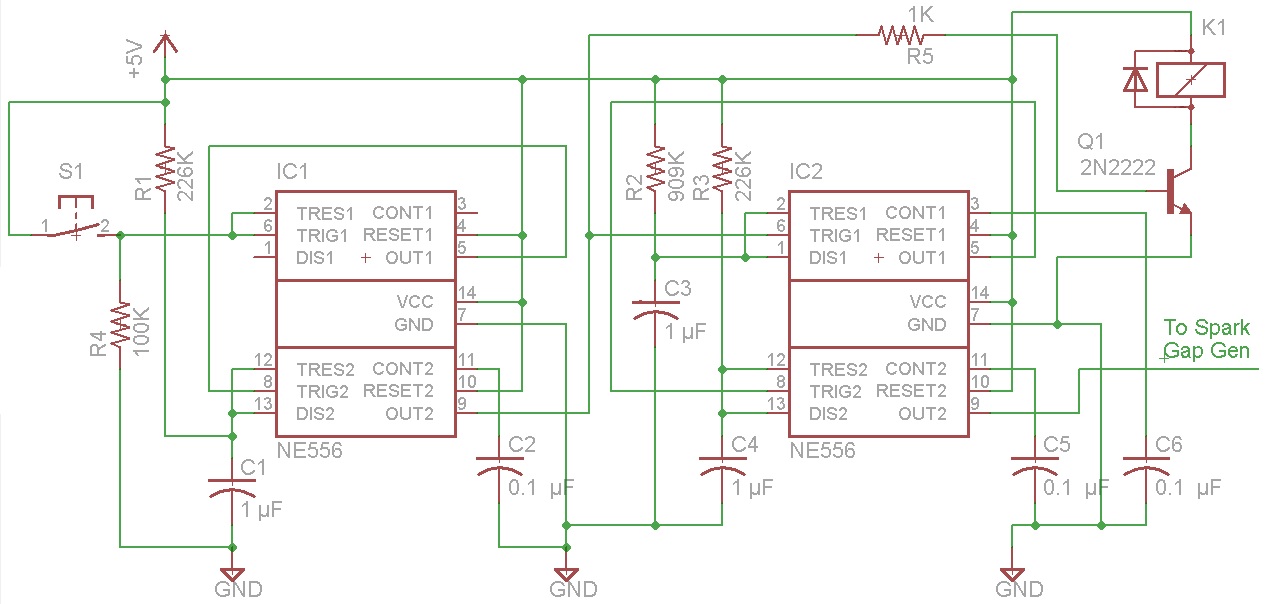
Here is a circuit using two 556 (dual 555) timers that I believe meets your needs. The 556 is available in a 14-pin DIP package.
enter image description here

The top half of the first 556 (IC1) acts as a Schmitt trigger to clean up any noise bounce from the pushbutton.

The bottom half of IC1 provides a 1/4 second output. It goes high when the pushbutton is pressed. It's output is fed to the solenoid K1. I have the solenoid connected to 5v, but you can connect the top end to 12v or whatever voltage is needed. When the output falls, it riggers the next timer.

The top half of the second 556 (IC2) provides a one-second delay between the release of the solenoid and the beginning of the pulsed output to the spark gap generator. The bottom half of IC2 provides a 1/4 second output. It goes high when the one second delay is over.

I didn't know what that interface to the spark gap generator looks like so I just show an output line ("To Spark Gap Gen"). You could add another NPN transistor interface if you like. The output to the spark gap generator is also set at 1/4 second.
enter image description here

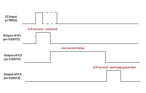
As shown in the timing diagram, the pushbutton can be pressed either for less time than the 1/4 second delay for the solenoid, or greater; in the lattter case the 556 timer will not re-trigger.

The times are all easily adjustable by modifying either the resistor values or capacitor values or both. C1/R1 controls the duration of the output to the solenoid (currently 1/4 second); R2/C3 controls the delay between the ending of the pulse to the solenoid and the beginning of the pulse to the spark gap generator (currently 1 second); and R3/C4 controls the duration of the output to the spark gap generator (currently 1/4 second).

I used this calculator to figure out the values of the resistors and caps needed.

By making any of these fixed resistor trimpots, you can adjust the timing to whatever you need.

I suggest using tantalum caps instead of electrolytic since you can twice as good tolerance (5% vs. 10%).

You will also want to add 0.1 µF bypass caps between the Vcc (+5v) and the GND leads (14 and 7) of each IC.

\$\endgroup\$
4
  • \$\begingroup\$ Fantastic answer. Holy shit! If it's this complex (and it's not meant for a production run, so BOM cost isn't an issue), why wouldn't I use an ATtiny85? \$\endgroup\$ Commented Sep 24, 2014 at 10:17
  • \$\begingroup\$ @RobertAtkins A microcontroller would work just fine for this. Although the schematic looks complex, it is actually a pretty small circuit comprising just two 14-pin ICs and some resistors and caps -- pretty simple to build on a perfboard in an hour or so. The advantage of the circuit, is using trimpots you can easily adjust the timing whereas with the program you would have to change the values in code and then reprogram the micro (assuming you don't have a user interface). \$\endgroup\$
    – tcrosley
    Commented Sep 24, 2014 at 10:32
  • \$\begingroup\$ I could also add trimpots on the analog pins of the Teensy :-). But I'm historically a software guy so that's the hammer I'm going to use. Thanks again. \$\endgroup\$ Commented Sep 24, 2014 at 10:40
  • \$\begingroup\$ @RobertAtkins Understand, I do both hardware and firmware myself (have degrees in both). Trimpots connected to ADCs would qualify as a user interface. Since in your question you said you were looking for a schematic, I assumed you were just interested in a hardware solution. Perhaps my circuit will be useful to someone else in the future. \$\endgroup\$
    – tcrosley
    Commented Sep 24, 2014 at 13:09
2
\$\begingroup\$

If you want to implement it in electronics rather than relays, search for:

  • monostable multivibrator
  • mono flop
  • single shot

One simple implementation is with a 555 timer IC.

\$\endgroup\$
1
\$\begingroup\$

This should work if I got what you meant, and here's how it works:

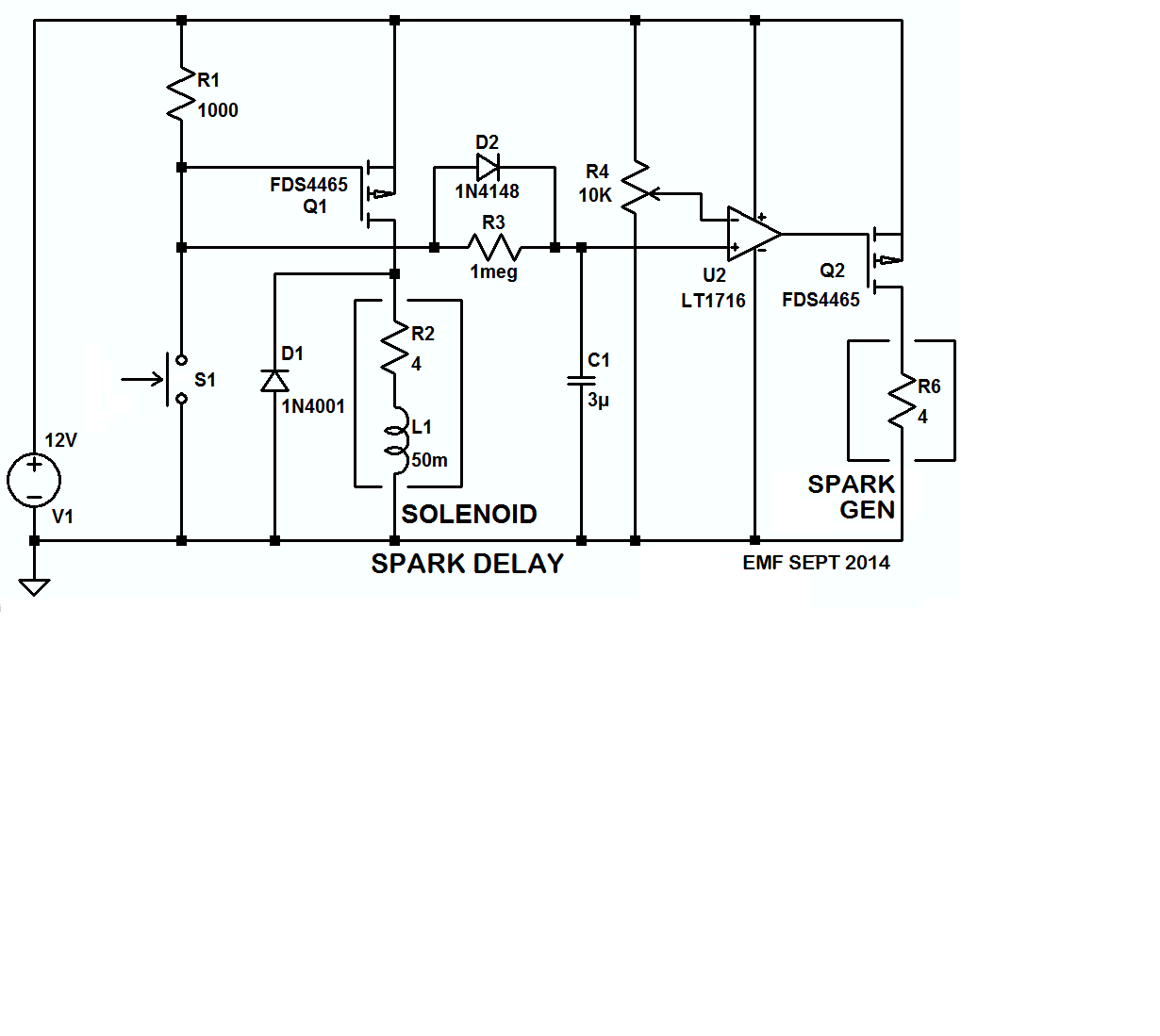
S1 is a momentary NO SPST (Form A) pushbutton switch, and when it's pressed the solenoid valve opens up and lets gas into a mixing chamber where it mixes with air and, a second or so later (adjustable by R4) the spark generator (igniter) is energized and ignites the mixture.

Thereafter, as long as the pushbutton isn't released, the solenoid will will stay open and allow gas into the chamber and the igniter will generate an arc, assuring the gas-air mixture will stay ignited. Then, when the pushbutton is released, the valve will close and the igniter will stop generating arcs until the switch is pressed again, starting the cycle anew.

The 4 ohm resistances for the igniter and the solenoid are based on your 3 ampere data, I assumed a 12V supply, and the 50 millihenry inductance for the solenoid coil was arrived at pretty much by WAG.

A simulation is here if you want to play with the circuit, and if you want to build it, DigiKey has all the parts in stock with the comparator and the MOSFETS going for about USD 5.00.

Also, if you build it, set R4 at midrange before you power-up for the first time, and then adjust it for the delay you want.

enter image description here

\$\endgroup\$
0
\$\begingroup\$

It would depend upon what your two circuits are, but most likely you will find something useful under "Time Delay Relay Schematic".

A relay is a coil-operated switch, by putting an appropriate current through the coil you can close or open one or many switch(es) (many different types exist).

\$\endgroup\$
0
\$\begingroup\$

Here, you can check for time-delay relays. With these devices, you can implement the activation of two o more circuits defining a delay time between activations.
For Time-delay relays, normally, two or four independent contacts, activated by the same coil are implemented.

\$\endgroup\$
0
\$\begingroup\$

Use an RC filter.

On hitting the button, you apply voltage to the two circuits. One is connected directly and reacts immediately. The other is connected through an R and then a C to gnd. The delay will depend on the turn-on voltage and your RC values. The voltage will rise 68% of the way every R*C seconds. You can make the R adjustable using a trimpot.

This is a passive low-pass filter.

\$\endgroup\$

Your Answer

By clicking “Post Your Answer”, you agree to our terms of service and acknowledge you have read our privacy policy.

Not the answer you're looking for? Browse other questions tagged or ask your own question.