1
\$\begingroup\$

What happens to a DSB signal Modulated signal if I use an envelope detector instead of Low Pass Filter ? I am interested in knowing how the output signals vary in case of a envelope detector. I know that I get the signal back in case of a low pass filter. Thanks for your time.

enter image description here

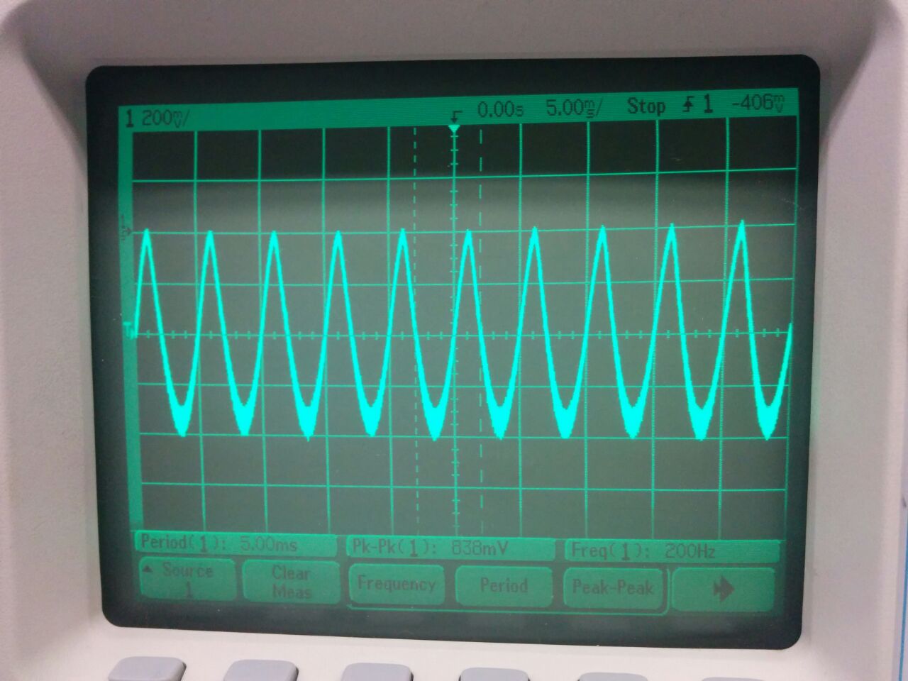
Envelope Detector enter image description here

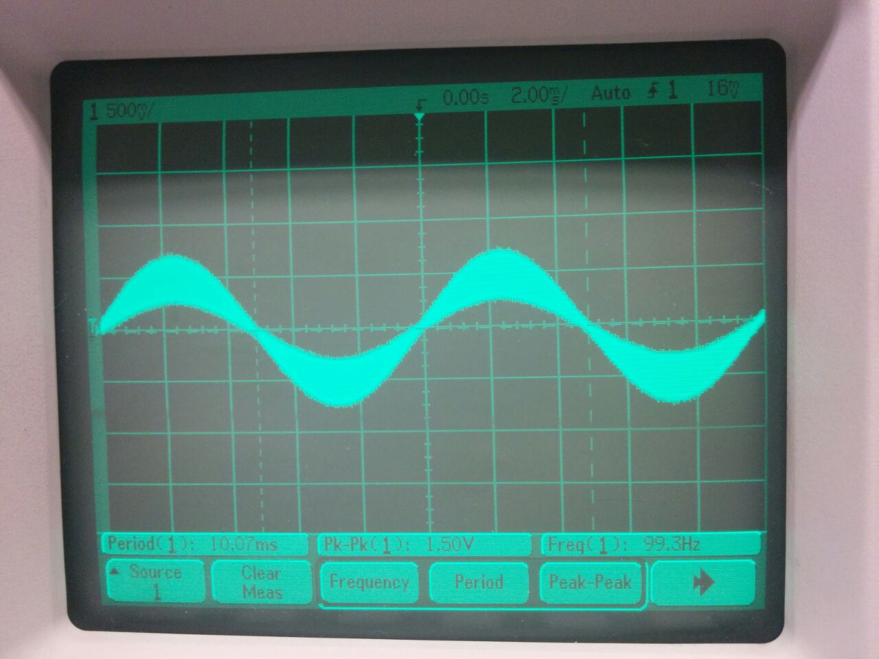
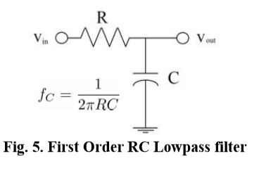
Low Pass Filter I used instead of the above envelope detector to retrieve the signal enter image description here
This was the message signal : 2 volts pk-pk cosine wave 100 Hz Carrier signal : 20 volts pk-pk 25khz

note that the when the low pass is connected the envelope detector is removed

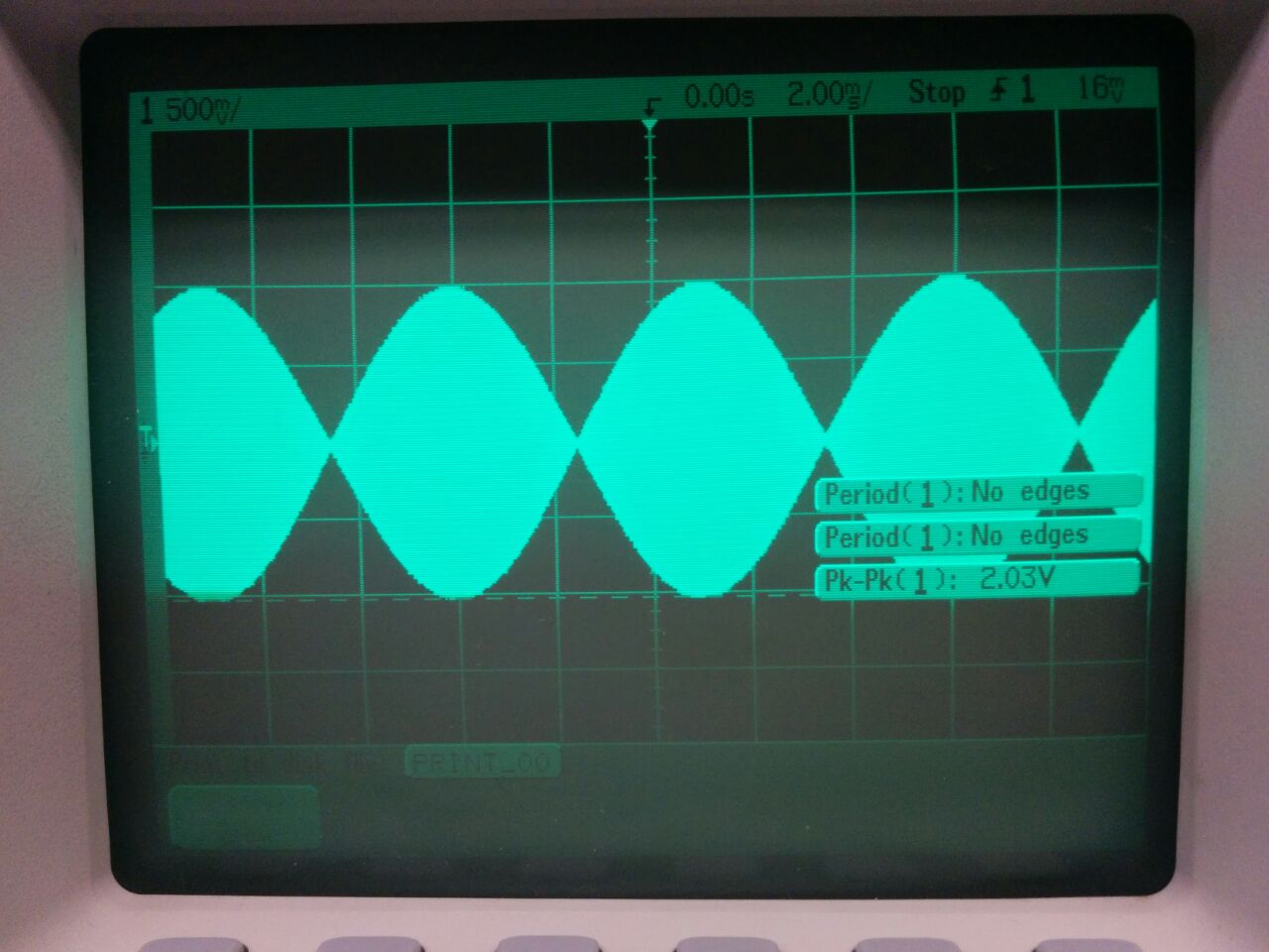
DSB Modulated signal enter image description here
OUTPUT From the Envelope Detector enter image description here

OUTPUT from the low pass enter image description here

\$\endgroup\$
5
  • \$\begingroup\$ The envelope detector in the figure, includes a low-pass filter (RC). \$\endgroup\$ Commented Oct 1, 2014 at 12:21
  • \$\begingroup\$ I have added the low pass filter i used. I believe that for low pass filter the c and r should be in series. Thanks \$\endgroup\$
    – Timmy
    Commented Oct 1, 2014 at 12:32
  • \$\begingroup\$ I obtained two different outputs in the lab so I was wondering what was physically happening. \$\endgroup\$
    – Timmy
    Commented Oct 1, 2014 at 12:32
  • \$\begingroup\$ Can you post the two outputs? \$\endgroup\$ Commented Oct 1, 2014 at 12:36
  • \$\begingroup\$ I will post it soon . \$\endgroup\$
    – Timmy
    Commented Oct 1, 2014 at 13:20

2 Answers 2

1
\$\begingroup\$

What you call envelope detector, consists of the detection diode and a low-pass filter. This is one way of demodulating an AM signal, more precisely, it is called asynchronous demodulation.

If you do not connect the diode, and only you process the AM signal with a low pass filter, you get the modulating signal, to which is added the carrier signal. Watch the third oscillogram well. It is the component of the modulating signal to the signal shaping, while is added a proportion of the carrier signal, attenuated by the filter.

The correct operation, is to use the envelope detector. The problem we are having is that the modulating signal is too high (amplitude), so when you make the detection and filtering, unwanted components appear, causing the distortion you see in the second oscillogram.

In the first oscillogram, one can see that the modulation index is extremely high; you should decrease the amplitude of the modulating signal and use the envelope detector to demodulate the transmission.

\$\endgroup\$
3
  • \$\begingroup\$ @ChrisStratton But this is the synchronous demodulation, using the carrier in phase. In the case of synchronous demodulation, there is no need of detection diode. Maybe the question is a bit unclear... \$\endgroup\$ Commented Oct 1, 2014 at 17:28
  • \$\begingroup\$ so you are saying that after demodulation and low pass filtration I will still have some of the components of the carrier in the message wave yes ? \$\endgroup\$
    – Timmy
    Commented Oct 1, 2014 at 19:07
  • \$\begingroup\$ There are basically two methods to demodulate an AM signal. The asynchronous demodulation, using a detection diode, followed by a lowpass filter. The other method, the synchronous demodulation, consisting in multiplying the signal modulated by the carrier, and then filtering. If the third oscillogram, corresponding to synchronous demodulation, you should decrease the frequency of the lowpass filter to improve the signal. You must no have carrier components y the demodulated signal. look at: midas.herts.ac.uk/helpsheets/tims/TIMS%20Experiment%20Manuals/… \$\endgroup\$ Commented Oct 1, 2014 at 19:19
0
\$\begingroup\$

In theory, if \$m(t)\$ is the modulating signal, then the ouput of the envelope detector (which is a rectifier plus an RC circuit) is \$A|m(t)|\$, the absolute value of \$m(t)\$ with a certain amplitude \$A\$ which depends on the input amplitudes and the gains/losses in the rest of the circuit.

\$\endgroup\$
2
  • \$\begingroup\$ Yes you are right about the amplitude A. But I am trying to evaluate the experimental results I obtained by using the low pass filter and the envelope detector. \$\endgroup\$
    – Timmy
    Commented Oct 1, 2014 at 19:16
  • \$\begingroup\$ @Adi: I understand. My point was that, since the output you're obtaining is not similar to a rectified cosine wave, there's some problem in your demodulator. If you know what to expect, you can evaluate your experimental results. \$\endgroup\$
    – MBaz
    Commented Oct 1, 2014 at 21:03

Your Answer

By clicking “Post Your Answer”, you agree to our terms of service and acknowledge you have read our privacy policy.

Not the answer you're looking for? Browse other questions tagged or ask your own question.