I am attempting to design an envelope detector, however, I'm having problems with regards to diagonal clipping and negative peak clipping of a certain input.
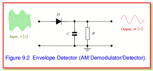
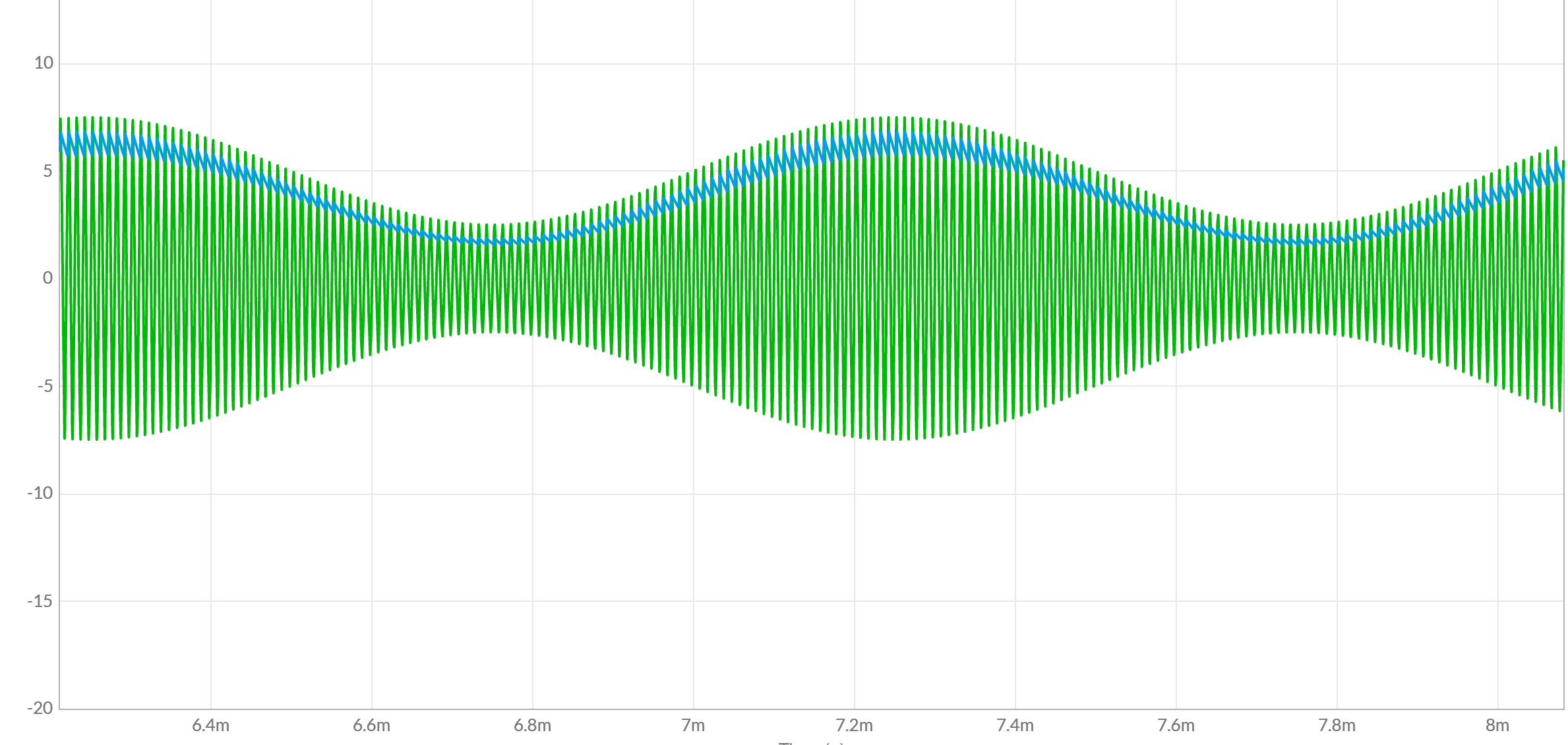
While trying to follow this video's simulation file, without modifying its input, I noticed that there isn't a lot of hassle when picking for the RC values since the modulation index was okay for the input wave.
Input:
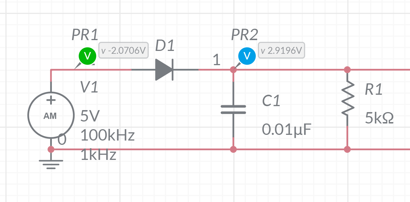 (modulation index: 0.5)
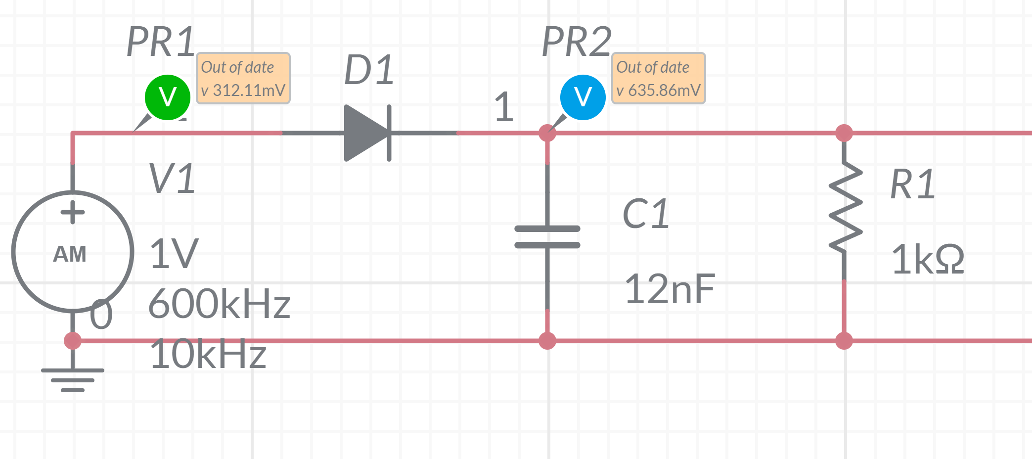
However, I am unsure of what RC values to choose when my input is: $$f_m = 10kHz\quad f_c=600kHz \quad \text{amplitude}=1V \quad \text{modulation index}=0.5$$
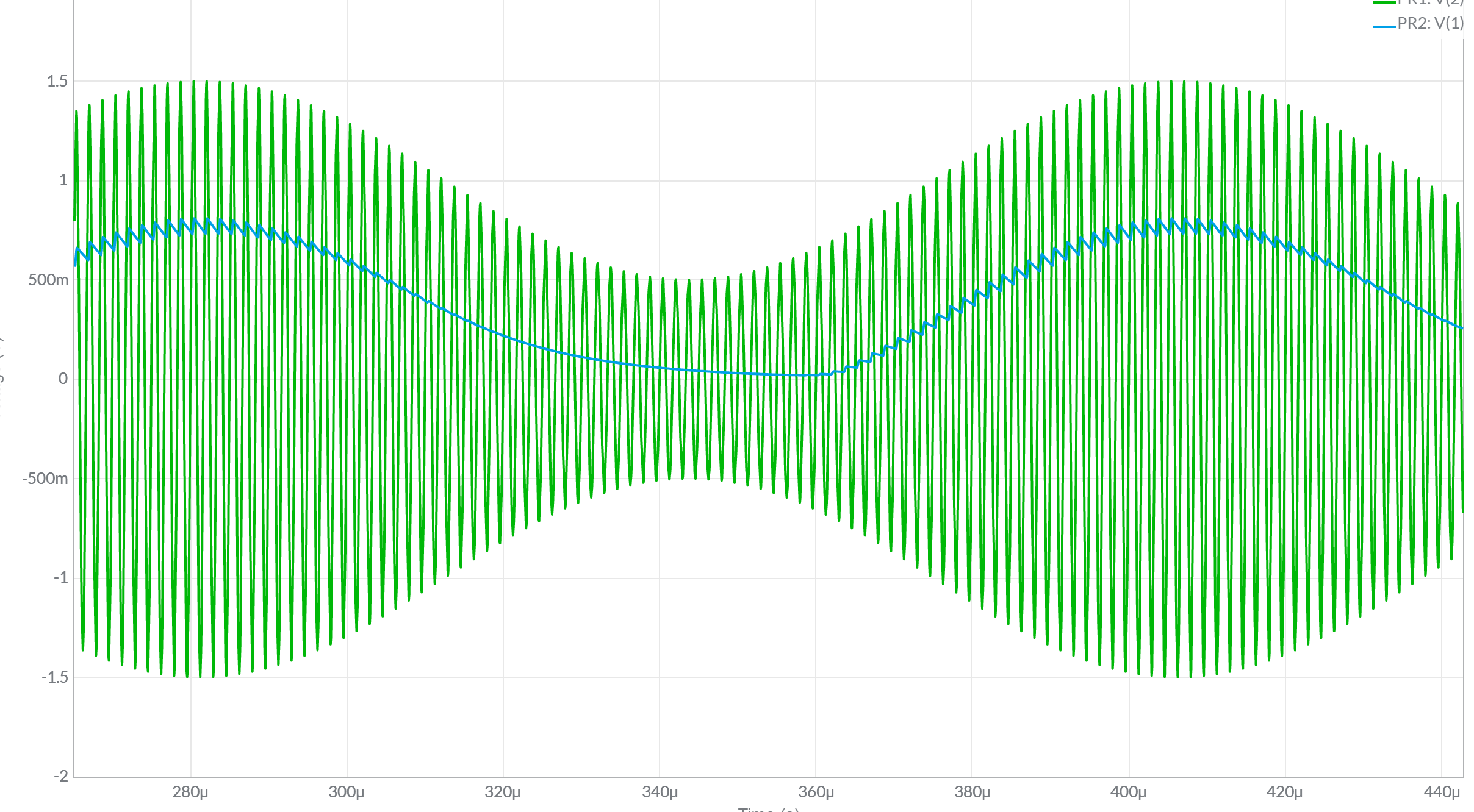
I first tried getting the geometric mean of my messenger frequency and my carrier frequency but the plot shows that these values large
I then tried lowering my RC value in an attempt to fix the diagonal clipping, but as seen on the plot, the output still isn't a clean sine wave (compared to the very first output. Decreasing the RC values further would then result to negative clipping and ripples on the upper portion of the output.
Some questions I want to ask are:
- How do I get the RC values that would still maintain the shape of the envelope given the input? Is it possible to do so without adding components to the envelope detector?
- If it is not possible to get the optimal RC values, is it still possible to retrieve the message in later stages? (i.e. inputting the output to a high pass filter/low pass filter or amplifier)

