1
\$\begingroup\$

I am driving an air core motor using PWM control from a microprocessor. The position of the air core is dictated by the combined magnetic field created by applying 2 currents to 2 coils (sine coil and cosine coil):

tan theta = Isin / Icos
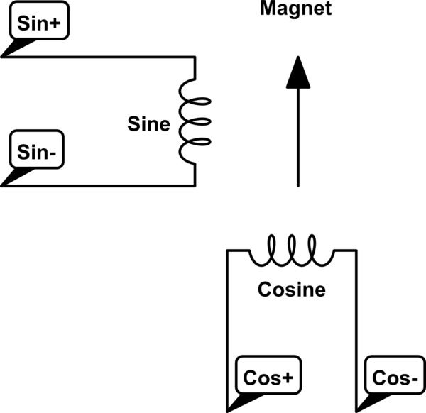
schematic

simulate this circuit – Schematic created using CircuitLab

The current in each coil is being created by PWM - the maximum PWM duty cycle is 75% and the minimum is 0%.

As I slowly change the values of the sine and cosine currents through 360 degrees, the magnet follows the desired position very nicely. However, around the 0, 90, 180 and 270 degree positions, the needle slows down as it passes through the quadrantal position then speeds back up to the normal rate of change in position (even though I am changing the desired position at a constant rate [0.1 degrees change per step]).

My question is, can you think of a reason why this is the case?

EDIT: Having inspected the air core, the magnet is surrounded by both coils, as shown.
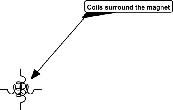
schematic

simulate this circuit

The physical arrangement is shown here:
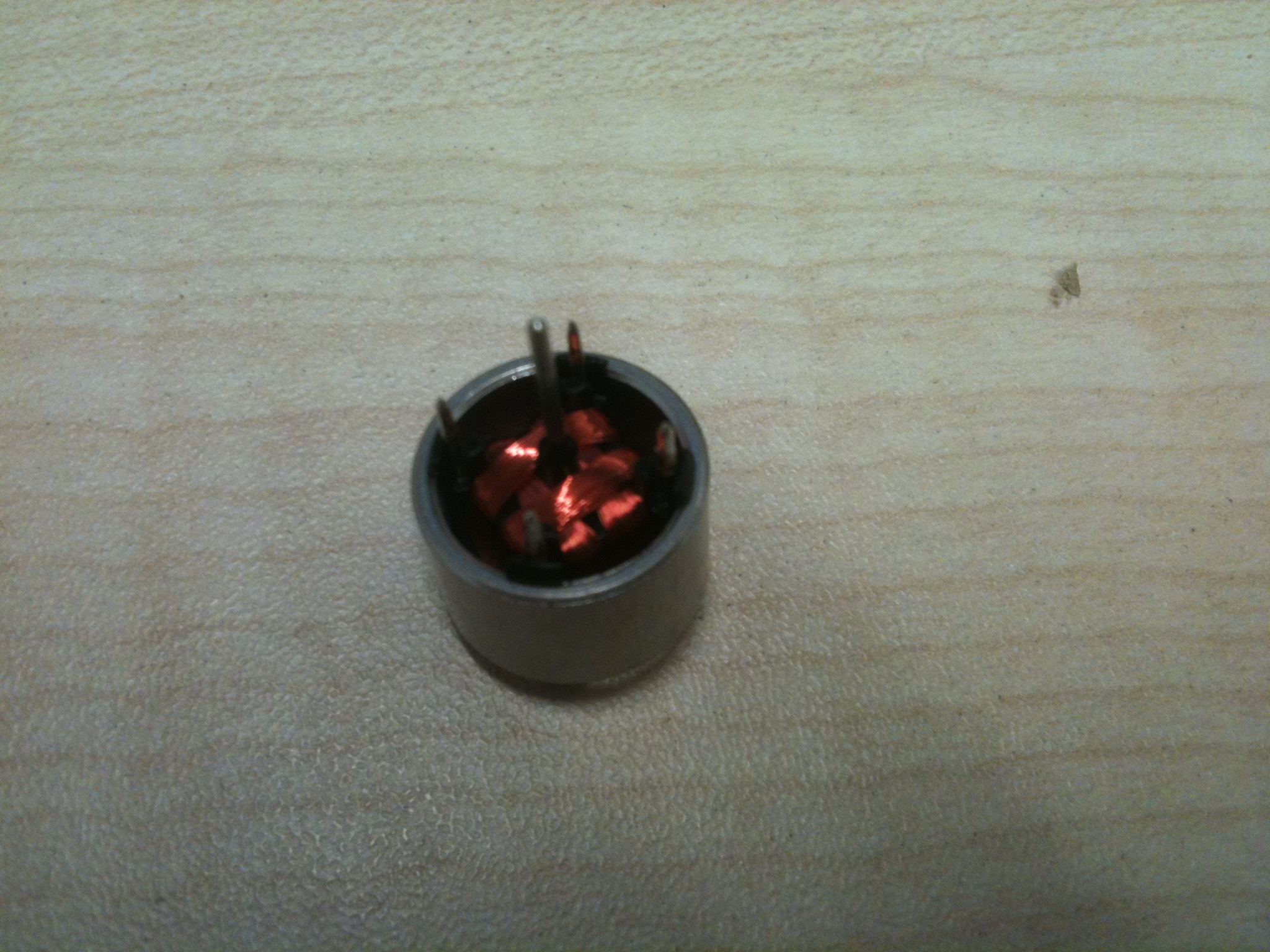
enter image description here

The patent here (PWM driver patent) describes an issue that appears similar, however, it is caused by a microprocessor being unable to accurately generate a PWM waveform when close to 0% and 100% duty cycles (back in 1991). We have a hardware PWM module, so there is no issue with this.

What is the force on the needle? Is it constant throughout 360 degrees rotation, or does it vary according to its angular position?

We are attempting to change the desired position (combined magnetic field of the coils) at a constant rate. It looks almost as though the force on the needle is less when it is nearly aligned with one of the coils and when the desired position is not close to being aligned with one of the coils that the force is greater.

\$\endgroup\$
6
  • \$\begingroup\$ The problem is as described here: forum.arduino.cc/index.php/topic,22480.0.html \$\endgroup\$
    – John
    Commented Oct 2, 2014 at 18:37
  • \$\begingroup\$ The answer might be ... Yes. Which isn't very helpful. But then we don't know anything about the geometry of the coils or their position relative to the rotor. I would only expect smooth motion if you can guarantee a constant field for each coil across the whole space the rotor occupies. One way to achieve this is for each coil to completely surround the motor. \$\endgroup\$
    – user16324
    Commented Oct 2, 2014 at 19:00
  • \$\begingroup\$ @BrianDrummond - yes, I've inspected the device and the coils physically surround the magnet: I've added a new diagram. \$\endgroup\$
    – John
    Commented Oct 6, 2014 at 9:43
  • \$\begingroup\$ @John - the new diagram doesn't help explain anything about what Brian said above i.e. physical geometry. \$\endgroup\$
    – Andy aka
    Commented Oct 6, 2014 at 9:53
  • \$\begingroup\$ I've added a photo - the coils literally do surround the magnet, apart from the area that allows the shaft of the magnet to exit the coils. The revised diagram I've posted should be seen as a literal diagram of the physical configuration. \$\endgroup\$
    – John
    Commented Oct 6, 2014 at 10:03

4 Answers 4

3
\$\begingroup\$

"appears to be a reduced force on the magnet when the magnet is close to being aligned with one of the coils, but no-one has explained why this might be the case"

When the magnet is aligned with one of the coils, the field lines go straight along the length of the magnet and there is no off-magnet-axis component of the field from that magnet to generate sideways force. This is so even though the coil current is at its maximum and is producing its greatest field strength. For any disturbance, the restoring torque will be very low because of this alignment. On top of that, the other magnet will be at the current crossover point and will be generating zero field, so it won't be doing anything to stabilize the magnet position either.

At 45 degrees both magnets are active at 71% of their maximum field strength and the magnet is being held in position by the vector sum of two fairly strong off-magnet-axis fields. If it is perturbed, the restoring force per degree of perturbation is much greater.

Electrical engineering is not my specialty, but I built my first DC motor out of wood, nails & scrap wire when I was in primary (elementary?) school 60-odd years ago.

\$\endgroup\$
1
\$\begingroup\$

I'm wondering whether the problem is possibly related to the actual current that flows through the non-aligned coil, as a result of the time constant of the coils.

Frequency of PWM = 150 Hz, giving a period of 6.67ms. In order to keep the current within limits of the coils, I had been using a max duty cycle of 75%.

The time period T of the coils has been measured at ~16.8us. Therefore for duty cycles with an ON time of less than ~80us (5T), the current will not get to the maximum it would get to otherwise, based on the R of the coil and the driving voltage. Force on the needle is related to current.

When driving the coil between 0-75%, a 80us ON time = a duty cycle of 1.199%, which equates to a position of ~0.9degrees. This is about the point at which the needle was observed to slow down, i.e. I am postulating that the inductance of the coil is now causing a reduction in the force on the needle when the needle is nearly aligned with any one of the coils.

A solution, if this is the problem, would be to reduce the time constant of the coil or to increase the period of the PWM, so that small duty cycles are larger than the coil time constant. The PWM frequency is 150Hz, and below about 100Hz there is vibration, so I think I've got this as low as I can, perhaps I'll try 120 Hz or so.

Next step to try (and I'll update this answer later), is to consider the coil to be a perfect inductor and a series resistance (time constant T = L/R). Therefore, if I increase the series R (by adding another resistor and increasing the voltage, I can get a smaller T but identical I through the coil). This smaller time constant should mean that the angular position where there is a slow down in the needle is much reduced.

UPDATE:

By reducing the time constant of the air core (by adding a parasitic resistance in series) and by increasing the PWM duty cycle and voltage (to keep the peak current constant), the situation was found to improve. However, there was a limit of perhaps 120Hz, below which there was significant vibration of the air core needle. The vibration was audible. There was always a small hesitation of the needle at the 90/180/270/360 degree points when the needle was travelling slowly.

I therefore believe that there is a fundamental issue with driving an air core needle using PWM when the needle is close to being aligned with one of the coils and that it seems possible to alleviate the situation but not to remove it entirely. The situation is entirely bearable if the needle is moving relatively quickly, but when it is moving slowly the problem is noticeable.

The situation was fixed by using a different method. The PWM waveform was fed through a low-pass filter, which gives a continuous voltage waveform rather than a switched average. The voltage is then fed to an op amp which drives a current amplifier. This current amplifier then drives the coils in the air core (there is no need for resistors in series any more, as the time constant of the coils is no longer an issue as we are driving with a constant current waveform). There is no identifiable hesitation in the movement of the needle throughout 360 degrees of rotation. By using a PWM signal beyond human hearing (we use 30 kHz), the driver is completely silent.

\$\endgroup\$
0
\$\begingroup\$

You are using two coils at 90 degrees to to create a spinning magnetic flux so that your magnet (needle) aligns with it yes?

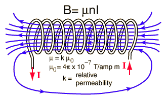
I think the problem is largely the way the flux density from each air cored coil is almost constant (close to and across) the face of each coil. Outside the "projected" tube formed by the coil, the flux varies with distance at a much steeper rate and round about halfway between the two quadrature coils the change in flux per angle turned will be quite linear: -

enter image description here

Looking at the picture above you can see that the density of the lines of flux at the ends of the electromagnet (solenoid) is fairly constant. This means for a given excitation current in the coil you'd measure near enough constant flux density across the "projected" face of the solenoid. You are then reliant only on the reduction or increase in flux from the non-aligned coil to move the needle. As this coil is now a significant distance from the aligned coil, the flux density it produces is much less.

I guess this is the problem of an air cored motor like you describe. If you looked at a more conventional motor, its stator windings are really close to each other: -

enter image description here

In addition to them being close to each other, the mag field is distributed by the iron core making the problem you describe very minimal.

\$\endgroup\$
4
  • \$\begingroup\$ Having physically inspected the air core, the 2 coils actually surround the magnet, so the magnet is in the middle of the linear flux area shown in your first picture. The patent here (google.com/patents/US4991098) describes a similar issue, but its genesis is in a software controlled PWM waveform that is difficult to manage when close to 0 & 100%. We are using a hardware controlled PWM waveform, so there is no issue with the microprocessor being unable to create the appropriate PWM duty cycle. \$\endgroup\$
    – John
    Commented Oct 6, 2014 at 9:41
  • \$\begingroup\$ @John so, what you are saying is..... \$\endgroup\$
    – Andy aka
    Commented Oct 6, 2014 at 9:51
  • \$\begingroup\$ I'm saying that others appear to have experienced a similar problem with what appears to be a reduced force on the magnet when the magnet is close to being aligned with one of the coils, but no-one has explained why this might be the case. \$\endgroup\$
    – John
    Commented Oct 6, 2014 at 10:14
  • \$\begingroup\$ @John - I'm not surprised the force is not linear (as per the reasons I give) \$\endgroup\$
    – Andy aka
    Commented Oct 6, 2014 at 10:24
0
\$\begingroup\$

I think using PWM to drive inductors is what is causing your problem.

When the PWM on the X axis is close to 100%, there is more time for current to build up and reach the maximum. At the same time, PWM is minimum on the Y axis, so the current cannot build up to the maximum during the On time.

PWM percentages only work correctly in resistive circuits that reach maximum current essentially instantly, with respect to PWM frequency. Remember, an RL circuit charges current exponentially, like an RC circuit charges voltage exponentially.

I'd send the PWM through a lowpass to smooth it to an analog value, then use that through an Op Amp buffer to drive the motor coils.

\$\endgroup\$

Your Answer

By clicking “Post Your Answer”, you agree to our terms of service and acknowledge you have read our privacy policy.

Not the answer you're looking for? Browse other questions tagged or ask your own question.