6
\$\begingroup\$

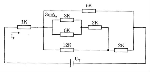
I'm studying about Ohm's Law, and the following problem perplexed me.

Schematic

The answer is \$I_{t} = 11\$mA and \$U_{r} = 41\$V.

What I need to find is \$U_{t}\$ and \$I_{t}\$. The only thing I've found so far is the total resistance:

$$R_{t}=\dfrac{41}{11}\Omega$$

Can you help me to understand it?

\$\endgroup\$
7
  • 1
    \$\begingroup\$ The 3mA are are through the 6K resistor or the 3K one? \$\endgroup\$
    – Adam
    Commented Nov 10, 2014 at 21:05
  • \$\begingroup\$ I guess it flow through the parallel 3k and 6k Ohm. \$\endgroup\$
    – mastergoo
    Commented Nov 10, 2014 at 21:06
  • \$\begingroup\$ If you don't know then I must assume that it flows through the 3K. It won't be the same current in the 6K. \$\endgroup\$
    – Adam
    Commented Nov 10, 2014 at 21:07
  • \$\begingroup\$ Ok, sorry Adam, the picture is ambiguous. \$\endgroup\$
    – mastergoo
    Commented Nov 10, 2014 at 21:09
  • 1
    \$\begingroup\$ I calculate \$R_{T} = 41/11\text{k}\Omega\$. You need to add the \$1\text{k}\Omega\$ resistor to your result and remember the resistances are in k\$\Omega\$. This would agree with the answers given. \$\endgroup\$
    – Null
    Commented Nov 10, 2014 at 21:11

2 Answers 2

12
\$\begingroup\$

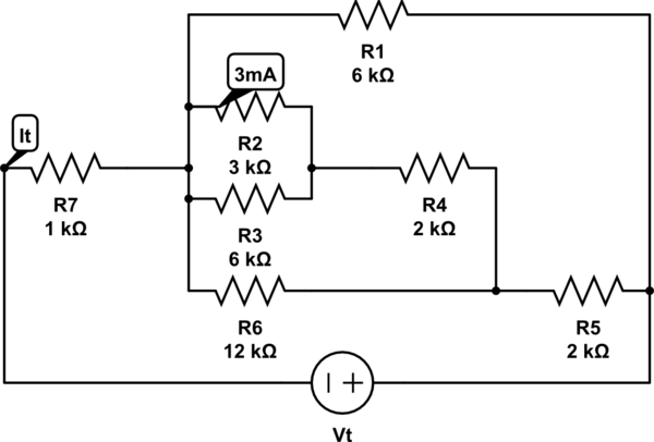
Well, I just calculated the currents and voltages and I get the same results as you quote. So how did I work it all out? Well, let's re-draw your circuit with better labels, and reduce it as we go. We start with:
schematic

simulate this circuit – Schematic created using CircuitLab

Ok, so we know 3mA flows through R2, which is 3000Ω. So the voltage across that resistor must be \$V=IR = 0.003×3000 = 9V\$. So there must also be 9V across R3 since it's in parallel. So \$I=\frac{V}{R} = \frac{9}{6000} = 1.5mA\$.

So R4 must be having the current that is through both R2 and R3, which is 3mA + 1.5mA, so 4.5mA. Again, V=IR, so 0.0045 / 2000 = 9V over R4.

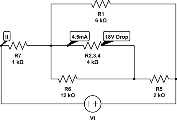
Ok, so let's simplify. Across R2||R3 is 9V, and across R4 is 9V, so across the lot there must be 18V:
schematic

simulate this circuit

Moving on... Your 18V known drop now also lies across R6, which is 12K. So that must have 1.5mA flowing through it. So what current flows through R5? The sum of R6 and R2,3,4's currents of course, which is 4.5+1.5 = 6mA.

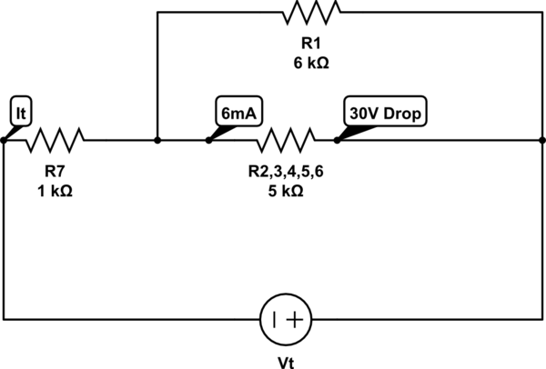
So now we can work out the voltage drop across that resistor at V=IR = 0.006×2000 = 12V. Therefore the voltage drop across the whole middle mess must be 18+12 = 30V. Time to simplify again:
schematic

simulate this circuit

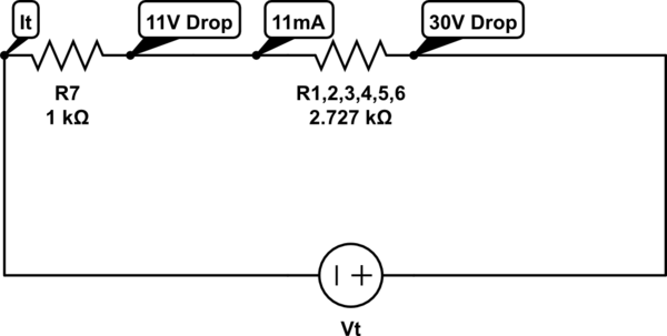
Ok, so we're now seeing a pattern. The voltage drop we just worked out is now obviously across R1 as well, at 6KΩ, so I=V/R = 30 / 6000 = 5mA. And again we sum the two branches to see what flows through R1. And that's 11mA (5+6). 11mA through a 1KΩ resistor is 11V. Shall we simplify one last time just for fun?
schematic

simulate this circuit

Ok, now it is obvious that \$I_T\$ is 11mA since that current must flow through both resistors. One answer now complete.

And the voltage must be the sum of the voltages dropped across the two resistors. 30+11 is 41V. Second answer done!

And for further confirmation, the total resistance is 2727.2727... + 1000 = 3727.2727..., and what else is 3727.2727...? 41/11 of course!

Doing this kind of circuit analysis is very much like doing a Sudoku. You have a few initial clue values, which lead to a few more values that you can infer from them. Those values in turn lead to more values, and so on, until you have filled out the whole grid.
\$\endgroup\$
4
  • 2
    \$\begingroup\$ Shame on you for giving the complete answer to a homework problem. It's good to explain the method, but the actual solution should be kept as a exercise to the student. In this case the "solution" is the method not the final answer, since the final answer was given up front. \$\endgroup\$ Commented Nov 10, 2014 at 22:09
  • 7
    \$\begingroup\$ Explaining the method in a way that the OP can understand (i.e., breaking it down into steps using their data) is nigh on impossible without giving away the answer. I could have used a different, though similar, circuit as an example, but I think the OP would learn better being helped through the one example. Maybe we could set some more for him to do to see what he's learned from it? \$\endgroup\$
    – Majenko
    Commented Nov 10, 2014 at 22:59
  • \$\begingroup\$ Really helpful, best answer ever. Thank you. I guess the main problem for me is the bad interpretation of the picture. \$\endgroup\$
    – mastergoo
    Commented Nov 11, 2014 at 16:04
  • \$\begingroup\$ @Majenko-notGoogle This kind of answer is the kind that puts my undergrad professors to shame. Thanks you! \$\endgroup\$
    – Funkyguy
    Commented Nov 11, 2014 at 18:29
5
\$\begingroup\$

You really should clarify this in your question, but the 3 mA is only flowing thru the 3 kΩ resistor. I got the correct answer of 41 V and 11 mA by starting with that assumption.

To solve this, start with what you know and work outwards. You know the current thru the 3 kΩ resistor, so you know the voltage across it by Ohm's law. That gives you the current thru the 6 kΩ resistor. Adding the two currents gives you the current thru the 2 kΩ resistor, which then gives you the voltage across it. No you have the voltage across the 12 kΩ resistor, etc.

Basically, start with whatever voltage or current you know and find the other by Ohm's law. The answer then tells you the voltage across or current thru some other resistor. You then solve for the other and repeat until you get the current thru and voltage across the whole network.

\$\endgroup\$

Your Answer

By clicking “Post Your Answer”, you agree to our terms of service and acknowledge you have read our privacy policy.

Not the answer you're looking for? Browse other questions tagged or ask your own question.