5
\$\begingroup\$

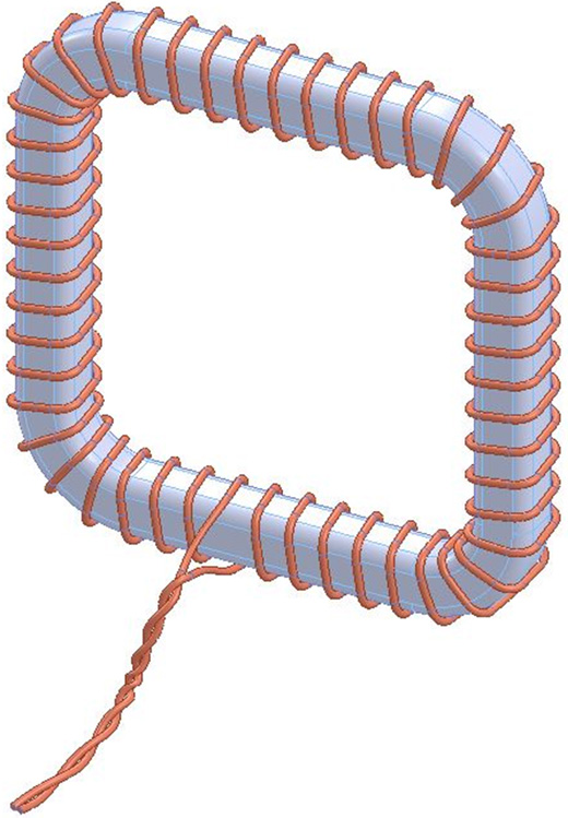
I sometimes see the wires of winding are twisted outside of the transformer (or inductor), as seen in the images below. What is the purpose of this? When should I twist winding wires and when shouldn't I?

As two conductors come closer and closer to each other, the capacitance between them increases. Wouldn't this parasitic capacitance between the wires cause problems at high frequency ferrite core inductors and transformers? Driving them will be the same as driving an LC tank circuit. There will be overshoots and ringing fluctuations. What trade-off does make us accept these side effects?
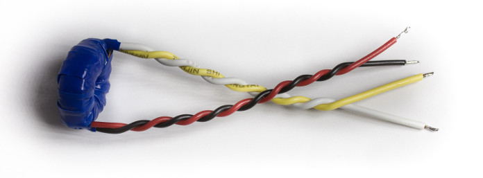
enter image description here

enter image description here

(Note: This is not about using multiple twisted wires as a single wire inside a winding (i.e.; Litz Wire).)

\$\endgroup\$
1
  • \$\begingroup\$ Normally twisting is done to reduce stray radiation/pickup and cross-talk. When wires of a more or less "balanced" circuit are twisted then any signal induced in one wire is also induced in the other, cancelling out. And any radiation from one wire is "matched" by radiation of the opposite sense from the other wire, again cancelling out. \$\endgroup\$
    – Hot Licks
    Commented Nov 16, 2014 at 5:05

3 Answers 3

7
\$\begingroup\$

Twisting the wires exiting a high frequency wound component (that might be carrying several amps) is a way of reducing the electromagnetic interference generated to other parts of a circuit.

\$\endgroup\$
2
\$\begingroup\$

Don't forget that the coil itself has a parasitic capacitance which may be much larger then the capacitance of the connection wires. In high frequency applications you have to look for short connections anyway.

Additionaly the twisted wires make clear which ones belong together and it looks neat.

\$\endgroup\$
0
\$\begingroup\$

Say you have 4 wires on a transformer, or a balun with 3 windings (6wires). Chances are, unlike your first picture, they are simply enamel coated wire...
Which one is which?
When you are installing the transformer, you can reach for a multimeter - but even then you will need to constantly check and re-check. You COULD add insulated color wires, as per your first picture. Then you just need to write down, or memorise, which colors are pairs.
Or, you can quickly twist pairs together, with the plan to UN-twist them (and cut them short) when you install the transformer.

\$\endgroup\$

Your Answer

By clicking “Post Your Answer”, you agree to our terms of service and acknowledge you have read our privacy policy.

Not the answer you're looking for? Browse other questions tagged or ask your own question.