0
\$\begingroup\$

I have two theoretical question about my circuit (that I have tested with a breadboard and it works, but I want to understand better some design choices):

1) As far the flyback diode is concerned, I have at my disposal 1N4007 high voltage diodes, that can be good because a 10x reverse voltage is suggested in these applications, or 1N5819 shottky diodes, that can be also good for the short reverse recovery time. The motor work at 12V, absorbing 5A. Between these two, what should be the best choice?

2) I have to determine the maximum frequency that I can use to drive my circuit, allowing the MOSFET to turn on and off completely without producing additional heat. The PWM circuit first goes into an ULN2803 darlington array, and then into an IRF9540 power mosfet. Considering the delay related to the two components, how to determine such a frequency? (I'm interested in how to compute the theoretical value, but working with a 25Khz PWM I shouldn't have problems, right?)
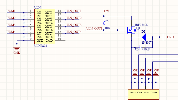
High Side PWM Motor Driving

\$\endgroup\$

1 Answer 1

2
\$\begingroup\$

Using R6 as the pull-up on a P channel mosfet is not great for efficiency of switching at higher frequencies. If the gate capacitance of the mosfet is 1nF then this and a 10k resistor form an RC circuit with a time constant of 10 micro seconds - generally, as a rule of thumb 5CR is a good estimate of how long an open-collector (ULN2803) digital signal takes to collapse when subject to an RC circuit and this looks like about 50 microseconds.

This on its own limits the highest frequency to 20kHz and in reality I wouldn't go above 5kHz with this. Maybe reduce R to 1kohm for operation at 25kHz.

Regarding the flyback diode, if the motor is taking 5 amps peak then a conservative approach suggests using a 5 amp diode but, given that a 1A diode will take peaks much in excess of 5A, you have to decide how much you are pushing the device to destruction. Every PWM cycle could push a peak current of 5A into the diode. Read the data sheets.

I wouldn't use a 1N400x because it sails just too close to its limits. You also don't need a diode that's rated at 1000 volts either in this configuration - 50% more than the supply voltage will suffice for this application.

\$\endgroup\$
11
  • 1
    \$\begingroup\$ +1. The problem with 1N400x diodes here isn't their current rating. Their reverse recovery time is so long that they don't really act as diodes at all, at PWM speeds. \$\endgroup\$
    – user16324
    Commented Dec 8, 2014 at 12:05
  • \$\begingroup\$ Too true @BrianDrummond!!! \$\endgroup\$
    – Andy aka
    Commented Dec 8, 2014 at 12:26
  • \$\begingroup\$ So 1N5819 shottky diode may work well? \$\endgroup\$
    – Daniel
    Commented Dec 8, 2014 at 14:24
  • 1
    \$\begingroup\$ No, this is still rated at an average forward current of 1A. If your motor were taking two amps and the diode was used 50% of the time then it would be OK. Your motor is taking 5A and I don't know what duty cycle the PWM is. I'd be looking for a 3A diode with the expectation it might be running at 40% duty but only you can tell us what happens. If you are on 10% duty then the current will never reach 5A but I can't tell what it will be. \$\endgroup\$
    – Andy aka
    Commented Dec 8, 2014 at 14:50
  • \$\begingroup\$ I was searching in the Internet, an SB5100 maybe can be the ideal for the application(since the duty cycle will be variable, even with an high percentage), right? \$\endgroup\$
    – Daniel
    Commented Dec 8, 2014 at 14:59

Your Answer

By clicking “Post Your Answer”, you agree to our terms of service and acknowledge you have read our privacy policy.

Not the answer you're looking for? Browse other questions tagged or ask your own question.