4
\$\begingroup\$

I'm more of a software engineer, but I've done a fair amount of toying with components and microcontrollers. That said, this has me concerned, and my searches so far seem to indicate that no one's ever had an issue with this.

I have a PIC12F675 - it has 6 I/O pins, and I need all of them. One will be an analog input, the rest LED outputs. And since I'll likely be soldering this to the board, I think the potential for ICSP would be of great use, to add features or fix bugs later. The only problem, as I have recently discovered, is that the VPP is something around 13 volts. On a pin that's connected to an LED. I'm not much of an electrical engineer, but I'm thinking the 220-ohm resistor isn't going to stop things from exploding.

What can I use to protect the LED, or other circuitry in general? I've got several of these chips, so I'm sure the issue will come up again, with components of varying sensitivity.

\$\endgroup\$
1
  • \$\begingroup\$ +1 For your explaining your work even if you are a beginner! \$\endgroup\$
    – 3bdalla
    Commented Jan 31, 2015 at 16:21

5 Answers 5

5
\$\begingroup\$

schematic

simulate this circuit – Schematic created using CircuitLab

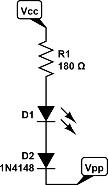
D2 can be any old PN diode, or Shottky. It will not conduct when Vpp goes above Vcc plus a diode drop, other than the spec'd reverse leakage current. That will probably be \$<10\mu A\$ depending on your diode choice. You'll turn the LED on by pulling Vpp low. Since you're adding another diode drop, R1 will need to be resized to allow the desired current to flow. Make sure you keep your LED currents within the device's absolute maximums.

\$\endgroup\$
1
  • \$\begingroup\$ This one wins, for being an embarrassingly simple solution with parts an electronics hobbyist may actually have on hand (or be able to salvage from a broken device). \$\endgroup\$
    – DigitalMan
    Commented Jan 11, 2015 at 4:47
2
\$\begingroup\$

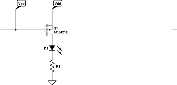
Here is one way to isolate Vpp:

schematic

simulate this circuit – Schematic created using CircuitLab

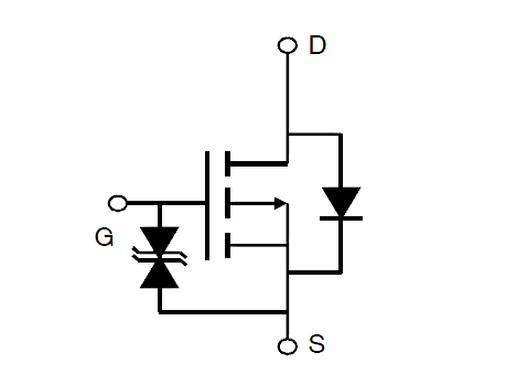
The particular part I mention (AO3421E) has internal gate protection and can withstand up to +/-20V Vgs.

enter image description here

This has the advantage over the simpler series diode (as @MattYoung has previously suggested) that if your LED has a high Vf (a blue or white LED) and your power supply voltage isn't very high, then the diode can make it difficult to safely get consistently high brightness because not enough voltage is dropped across the resistor. It's still just one component, albeit one with three leads and a bit more expensive.

On the other hand, if you like to live dangerously close to the edge and thrill at the thought of the occasional wisp of acrid fumes, many LEDs have an actual reverse breakdown voltage well in excess of 8V (13V - 5V) to 10V (13V - 3.0V) so your circuit might work fine as-is. No guarantees though. If it were to break down it could drive the Vcc supply up above absolute max voltage and damage the micro.

See, for example, this application note from Avago on reverse transient immunity of their LEDs. They did apparently see at least one LED that had a breakdown of ~-7V, and the guarantee on datasheets usually ends at -5V or -6V. I don't suggest it in general, but for something like a toy, I'd likely do it in an instant (and commit to keeping on top of the LED supplier, part number and any potential changes). As you can see, for many LED technologies -50V or even 100V is not a problem.

\$\endgroup\$
1
\$\begingroup\$

Geesh guys, step back and look at the bigger picture. This is clearly a hobby project, not for volume production. Just get a bigger PIC already, and then the programming lines don't have to conflict with anything.

Just for completeness, if you had share Vpp with MCLR or GP3, using a separate low side NPN transistor to drive the pin is often a easy solution. Note that this pin can only be a input. It can't drive a LED, for example. The pin itself is always high impedance. You can therefore drive it with something like 20 kΩ in series. Often it won't matter if the PIC end of that 20 kΩ is driven to 13 V during programming. Another thing to consider is that the programmer must also be able to drive the pin low. 20 kΩ is high enough that any programmer should be able to drive the line to whatever voltage it wants.

Also choose the pin functions carefully. Not only must the programmer driving these external functions not cause harm (note that the unit doesn't have to operate correctly during programming, just not be damaged), but you also have to consider that the programmer needs to be able to drive the lines to full logic high and low.

I go into more detail on this issue in my document In-circuit Serial Programming (ICSP).

\$\endgroup\$
0
\$\begingroup\$

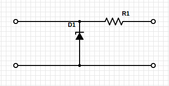
If you need a permanent non-jumper solution - consider protecting your analog voltage source with a simple resistor and a zener. The image shows your source on the left, and your PIC on the right. For a 5v setup, perhaps a 5.6v zener could be used?

The user manual for pickit recommends typical 450ohms pullup to protect Vpp - which gives roughly 12-5 volts over 450 ohms = 16mA load on the programmer.

enter image description here

To protect for similar current in this setup, let R = 12-0.7V over 16mA = minimum 720Ohm - i.e. 820Ohm. The zener will need to tolerate 0.7V * 16mA = 11.2mW - and your input must tolerate 5.6V supplied to its input and should have >> 820Ohm impedance...

If you need to fine tune the threshold, use a smaller Zener value, and add forward biased diodes on the zener cathode to lift in increments of 0.7V (depending on diode used)

\$\endgroup\$
0
\$\begingroup\$

Vpp-pin - GP3 - is input-only on 12f675, so you should look at the AN3 source to see if it can handle the voltage. You could consider a jumper if diodes de-linearises your input - which I suspect it could with A/D function on the input.

\$\endgroup\$

Your Answer

By clicking “Post Your Answer”, you agree to our terms of service and acknowledge you have read our privacy policy.

Not the answer you're looking for? Browse other questions tagged or ask your own question.