3
\$\begingroup\$

We are using a set of RS485 servo motors(Robotis EX-106) for our humanoid robot. EX-106 Motor Picture
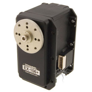
This motor has a 4 pin connections namely Ground,VCC, D+ and D-. The Ground and Vcc terminals are from the power supply which is a 15V supply.

Since the motors serve as joints for the Robots limbs, they are connected in a daisy chain to send the power and data lines to each motor with minimal wiring. A schematic of the setup is as follows
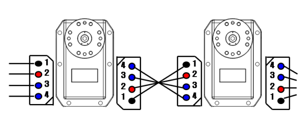
Daisy Chain Setup
(source: robotis.com)

So ideally the both the Power and Data lines reach all the motors in parallel.

With the premise set, here comes the problem.

At each node of the daisy chain(i.e. at each motor) there is a voltage drop. This voltage drop is low(0.2V-0.9V) but still significant.

For instance, with a 15 V supply, the values we get on measuring the voltage at 4 daisy chained motors is as follows(These values have been updated since the original post, with better observations)

15------[14.1]------[14.0]------[14.0]------[14.1]

Also from recent experiment , we see that the voltage drop is proportional to the number of motors in the daisy chain. For example for only one motor the drop is 0.2V, for 6 motors it's about 1V and for 12 motors we get about 1.8V of drop.

The first reason that comes to my mind is the voltage drop across the connecting wires. But I am not sure if the wires can cause a voltage drop of this value. All my wires are less than 20cm in length and 22 AWG in gauge size. I dont think the resistance will be more than a few milliOhms. Plus these measurements are during the no load phase(no load on the servo motors) and according to the Robotis EX-106 Manual, the no load current is only 55mA which needs atleast 10 Ohms of resistance for this amount of drop.

What could be the reasons for this? Is there any way to avoid this voltage drop?

I will keep the post updated as we discover more things.

\$\endgroup\$
3
  • \$\begingroup\$ I'd be less concerned about the actual wires, and paying more attention to the contact resistance of all those connectors and the drop across (the PCB of?) each motor. \$\endgroup\$
    – Dave Tweed
    Commented Jan 17, 2015 at 15:06
  • \$\begingroup\$ I did not understand if the drop across each connected motor is the same. i.e., if you measure voltage at M1 it's 15V, then M2 is 15-Vd, then 15-2Vd and at Mn you get 15-(n-1)Vd, is this right? When you chain 12 motors in the first part of your wiring you have some 0.6A flowing, is this taken into account? Plus that figure is ramping up when you are actually doing something with the servos. I second dave though, you can rule out wiring measuring the voltage drop between two "one terminals" and two "two terminals" of each servo. \$\endgroup\$ Commented Jan 17, 2015 at 15:28
  • \$\begingroup\$ There indeed could be a diode between the IN and OUT power connection. This is poor design, as a Back to Back PFET would have been far better for protecting the output while providing extremely low on resistance. If there are diodes, then the power rails are not "parallel" at all, they are series through the diodes and "branched" off into the motors at each stage. You most certainly should not have more than 3-4 servos chained like this, if that is how it goes! As someone else said, run the power cables (22AWG is terrible by the way. Get much larger gauge please) along and tap off for each one \$\endgroup\$
    – KyranF
    Commented Jan 17, 2015 at 16:17

2 Answers 2

3
\$\begingroup\$

Assuming your connections are correct, there may be a low Vf protection diode in each assembly. This would protect each servo system incase it was connected to a reverse power condition.

The voltage drop likely increases as the motor draws more current.

Does the specification sheet list a maximum number of servos connected in a row with this type of hook-up?

Rewiring just the power lines, using a continuous wire with multiple "T" drops, into each servo's input connector should solve the issue. (That is if the small voltage offset is really an issue.)

\$\endgroup\$
1
  • \$\begingroup\$ To prove or disprove the diode's existence you could use an ohm meter to measure the continuity of the side to side power pins. With the meter check the continuity from same pin name to same pin name, then reverse the meter leads and recheck the same two pins. An open circuit in one direction (but not the other) indicates a diode in the line. \$\endgroup\$
    – Nedd
    Commented Jan 17, 2015 at 13:37
1
\$\begingroup\$

I'm the asker of the question, the issue is solved, here's our experience about it.

I think we've figured out why we were facing the problems(we really hope we hope we have!). As mentioned in the question, the main issue was of an arbitrary voltage drop along the daisy chained line of motors.

The solution of using a T type connection(initially suggested by @Nedd) was what we finally turned to but it wasn't a diode which was causing the drops. It turned out to be something much simpler.

The servo itself has a high resistance element. Also our wire gauge for the power wiring was 22 or 24 AWG. These servo motors use a simple DC motor as the core actuator and a sophisticated control system for the servo function. Hence when there is some load the servo will draw more and more current. The daisy chain would mean that the first wire would carry current for all the subsequent N motors, the second would carry current for N-1 and so on. This high volume of current on our 22/24 AWG coupled with the motor's own resistance resulted in the voltage drop.

Also the no load current as mentioned in the manual is for fresh motors. It might be possible that some motors on the line are drawing more no load current due to overload damage etc. over time.

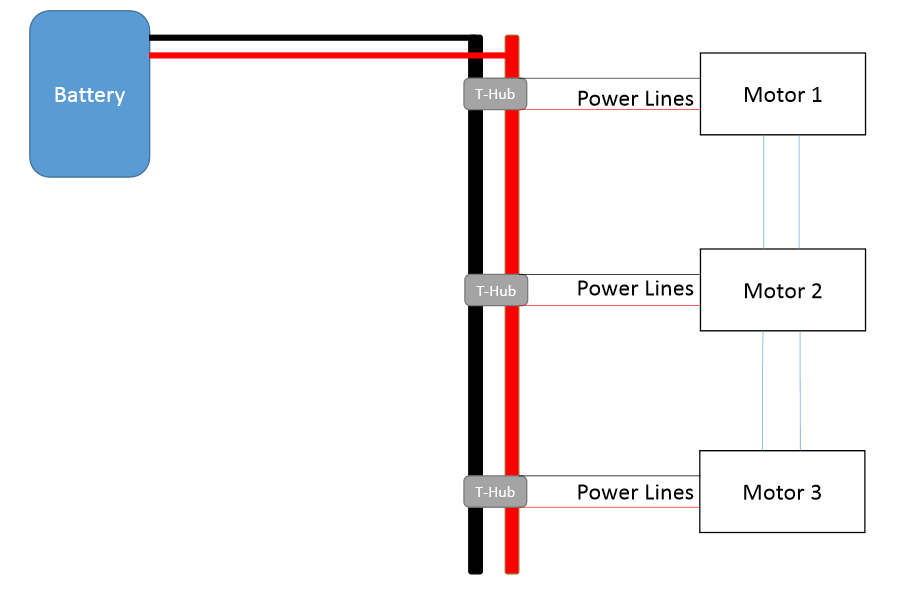
So our final solution was using a Tree based power distribution network where the central "Trunk" was made of think 16AWG wires. This also helped us in reducing voltage fluctuations along the whole bus. At each node, we have a T- Hub which would help us "Tap" wires from the motor(22-24AWG) onto the main power bus.

So each motor wire(22-24AWG) only bears current for one motor and the thick gauge wires carry the whole current.

Now the line works fine with almost no drop at each motor connection. :D

TLDR: discard the daisy chain and go for the tree arrangement

Heres a rough schematic I made to visually show what we did.

enter image description here

Do let me know if i can further clarify. I have put this answer since we were stuck on this problem for quite a long time before I even posted the question and this answer might help many other people working on this kind of system.

\$\endgroup\$

Your Answer

By clicking “Post Your Answer”, you agree to our terms of service and acknowledge you have read our privacy policy.

Not the answer you're looking for? Browse other questions tagged or ask your own question.