0
\$\begingroup\$

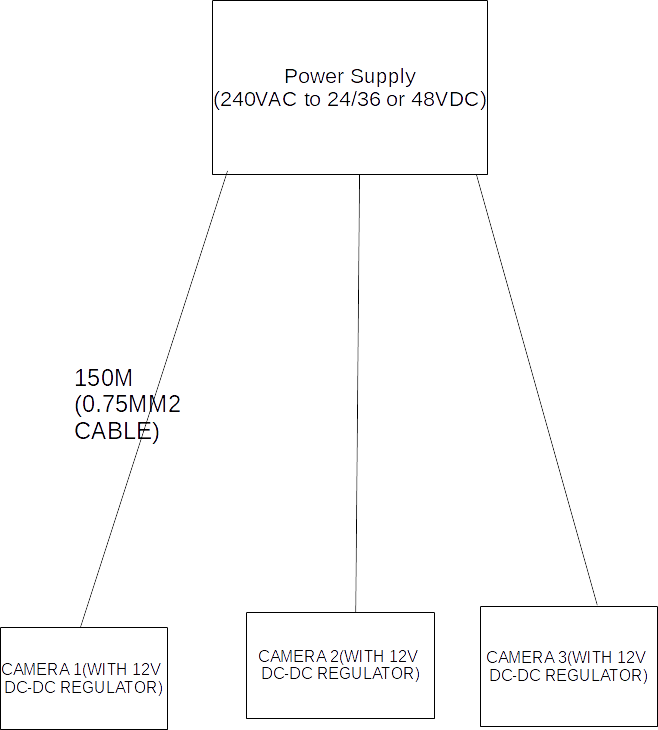
I am trying to calculate the power supply required for 3 cameras (1A each), each with 150 metres of cable (0.75mm2), connected to a common power source (AC-DC PSU).

I have done these before with single cameras, however I'm unsure how multiple devices affect voltage drop. Is voltage drop calculated using the entire length of the run (ie 450 metres-note the cameras are not daisy-chained, each 150m length of cable goes directly between camera and PSU) and the combined current draw (3A)? Or do you calculate each run separately (150m and 1A) and then add them together? Or, most likely, something different? Image added below

At each camera there will be a 12v regulator, but I'm unsure on what voltage I should start with.

Any help on how to proceed much appreciated. TIA![camera setup schematic]1
\$\endgroup\$
7
  • \$\begingroup\$ The full current travels to the 1st camera, a smaller current (reduced by what the first camera subtracted) continues to the 2nd camera, etc. You can work out drops involved for a fixed gauge or you can change the gauge as you go, I suppose. If you are able to support the idea of a regulator at each point along the line, then supplying a higher voltage than needed and using switchers at each node, would permit the use of a relatively lighter power cable. There are some very nice 19-wire silver cables which are flexible, durable with usage, and if used at a higher gauge would be okay on price. \$\endgroup\$
    – jonk
    Commented Dec 5, 2019 at 5:22
  • \$\begingroup\$ draw a diagram, it's not clear how you intend to connect your cameras and wire. However, with those lengths, higher voltage supply with a buck DC-DC at each camera would have a lot to commend it. \$\endgroup\$
    – Neil_UK
    Commented Dec 5, 2019 at 5:34
  • \$\begingroup\$ have added a diagram which hopefully makes the setup clearer \$\endgroup\$
    – UW2014
    Commented Dec 5, 2019 at 5:50
  • \$\begingroup\$ Your drawing shows the three cable runs as independent. The voltage drop in each cable only depends on the current and cable resistance in that cable. The power supply has to deliver the total current of the three loads. \$\endgroup\$ Commented Dec 5, 2019 at 6:45
  • \$\begingroup\$ thanks @PeterBennett. Thats where my confusion lies. So assume I calculate a 2V drop on each line, can I expect a 6V drop overall, or no? ie if I supply 12V, would I expect 10V at each camera, or 6V? I do understood that the PSU has to be able to supply the necessary current for all three cameras. Thanks again \$\endgroup\$
    – UW2014
    Commented Dec 5, 2019 at 7:06

2 Answers 2

1
\$\begingroup\$

You have to compute the voltage drop on each wire based on the current actually flowing on that wire.

So the answer is, you compute them individually and don't add them together.

Given your simple "star" topology, this gets fairly easy. Since both wires are of equal size, you can compute the voltage drop on any run-of-the-mill voltage drop calculator on the Web that's intended for residential wiring (just make sure they give sensical numbers for low voltage; or tell them 120V and use the absolute drop number, which will be the same for any voltage). Example from this calc:

  • 150 metres
  • 1 amp
  • 14 volts
  • 20% voltage drop allowable (giving 11.2V)
    • Answer: 14 AWG wire gives at 1A 18.84% drop of 2.66V, giving 11.34V.
    • Voila, no regulator needed as I'm sure the camera can tolerate both 14V and 11.34V.

AWG 14/2 cable is pretty much the cheapest cable you can buy, because of the economies of scale of mass production use in residential wiring. If you're in Europe you could recompute for 1.00mm2 or 1.5mm2 wire.

You can also solve this by kicking voltage up to mains voltage (e.g. 120/230V) or even higher (I push it as high as 480V). This will virtually eliminate voltage drop for a 12 watt load. However, if you do that, you must now use "Class I" wiring methods or whatever your jurisdiction requires for mains power, and this is rather burdensome. It also creates life-safety issues if water or damage to cables is involved in any way.

\$\endgroup\$
3
  • \$\begingroup\$ aha, thanks, so in your example, there will only ever be a 2.66V drop, regardless of how many cameras were connected to the system?ie a power supply supplying 14V to one camera, is just as suited (assuming it can output the current) to supplying multiple cameras? \$\endgroup\$
    – UW2014
    Commented Dec 5, 2019 at 7:02
  • \$\begingroup\$ @UW2014 As long as each camera has its own 150m "home run" cable, that is true - the "home run" cable is where the drop happens, after all, and each camera has its own, so it only suffers its own drop. Keep in mind I am presumng a much larger wire for economy-of-scale reasons, 14 AWG is 2.08 mm^2, not the 0.75mm^2 you are proposing. That seems unworkably small, and is an odd wire size, and I suspect will be more expensive than common mains sizes like 1.5mm. \$\endgroup\$ Commented Dec 5, 2019 at 7:23
  • \$\begingroup\$ ok thanks! Understood regarding wire size. 18AWG is the size we use in a custom cable. \$\endgroup\$
    – UW2014
    Commented Dec 5, 2019 at 8:13
0
\$\begingroup\$

You can use online calculator tools for that, a 150meter 0.75mm2 cable 1A would yield a voltage drop be about 10V which is basically unusable.

It is not a good idea to power devices over long cable using small voltage / high current.

The correct approach is to have 110/230VAC over the cable and then at each location to have a small 12VDC power supplies (those are dirt cheap).

\$\endgroup\$
4
  • \$\begingroup\$ Thanks, you may be right, however running 240V is not an option here. I could supply 24VDC or more, which more than accounts for the the 10V of drop. However I'm unsure how to calculate the initial supply voltage required with multiple devices (ie is the voltage drop a sum of each one individual run?) \$\endgroup\$
    – UW2014
    Commented Dec 5, 2019 at 6:13
  • \$\begingroup\$ I'll be the first one to kick it up to 240V or even 480V for long hauls. (my specialty is using #14 for jobs that call out #2/0). But I don't agree that's always the right answer: that forces you into Class I wiring methods, which are much more burdensome and totally new skill-set for LV electronics types. @UW2014 Drop isn't consistent like that, though. Drop (E) is based on resistance (R) of the wires *and the current actually flowing in this instant (I). E=IR. As I varies, E varies in proportion. So you can't use a long wire run as a voltage divider. \$\endgroup\$ Commented Dec 5, 2019 at 6:39
  • \$\begingroup\$ @UW2014 if you need to transfer 12W over 150 meters, increasing the voltage will be your only solution, or run 4mm2 wire that is going to cost you big bucks. \$\endgroup\$
    – Damien
    Commented Dec 5, 2019 at 7:32
  • \$\begingroup\$ great, thanks very much \$\endgroup\$
    – UW2014
    Commented Dec 6, 2019 at 1:01

Your Answer

By clicking “Post Your Answer”, you agree to our terms of service and acknowledge you have read our privacy policy.

Not the answer you're looking for? Browse other questions tagged or ask your own question.