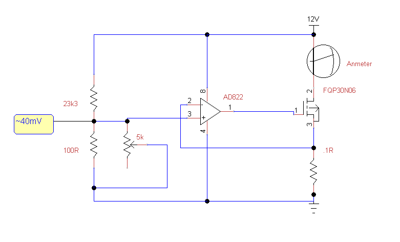
I've been playing with various constant current source configurations to help control the current output of my bench power supply and my latest efforts centred around the op amp and MOSFET approach. I breadboarded the circuit shown below and got a pretty reasonable max Vref of 40mV at the + input to the op amp and both op amp inputs had equalized, so things looked good. Keen observers will notice the crucial missing components, but more on this later. I decided to wire up a current meter between Vcc and MOSFET to check the current, expecting < 1/2 an amp flowing through the MOSFET. I can't remember exactly what the current measurement was before I switched off the meter, but I don't believe it was high (probably a bit low, if anything).

A split second after turning off the meter (the circuit was still powered), the op amp went up in smoke. The MOSFET was very hot and the op amp was warm-to-hot. At first I thought it was the action of turning off the meter, but now I'm not so sure.
I considered that turning the meter off left the source / drain leg OC. This would have made Vsense 0V. The op amp would drive hard to make the - pin equal Vref, but so what?? No current is flowing through the MOSFET and the gate has a very high impedance, the op amp is putting out a high output voltage, but that shouldn't kill it surely and it's also a very valid test case for this circuit. The whole idea is that it protects against load shorts. If the circuit was operating correctly then a short between Vcc and MOSFET should still result in a controlled current through the FET. I started looking on the internet for other possible causes and I hit upon HF oscillation as a possible cause.
Here's my take of what may have happened: the capacitative load that is the gate of the MOSFET introduces a delay into the negative feedback loop. Starting with a Vsense voltage that is slightly too low, the op amp puts out a stronger output signal to correct the difference on its pins but this signal is delayed whilst the MOSFET gate charges. Now, I'm not completely sure what happens next, but the gate will eventually reach the voltage intended by the op amp and I'm guessing that the extra time spent charging the MOSFET gate causes the gate voltage to overshoot (is this true? what really happens here?). This causes a higher than Vref voltage to appear across Vsense and the op amp acts to correct this by pulling the output low. This causes the gate capacitor to discharge slowly through the op amp output, which again causes a delay since the effect of pulling the output low isn't appearing across Vsense as quickly as it should. So, we have oscillations back and forward, constant over and under shooting.
Using this analogy, I have glimpses of understanding around why placing a resistor between the op amp output and the MOSFET gate (and/or a capacitor between the op amp out put and ground) acts to reduce this effect, but it's by no means clear. So, here's my challenge to you guys with more experience and knowledge: can you provide a decent intuitive anatomy of this disaster so that I fully understand what happened (the word "pole" is banned!)? Can these oscillations really kill the op amp? I'm thinking that the amount of current sloshing back and forward between the op amp and MOSFET is quite small considering the capacitance involved. Also, can you explain in a nice intuitive way why the resistor and cap solution mitigates the problem?
