1
\$\begingroup\$

enter image description here

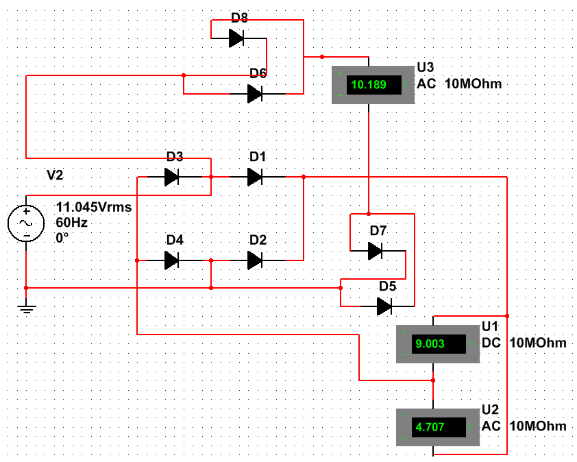
If I rectify 10Vac (rms) by diodes without a voltage drop to a full wave pulsating dc, the peak voltage would be Vrms x square root of 2 = 14.142135V The dc (average) voltage would be

2V peak/pi = 9.00316V,

And the ac voltage would be 4.35236V (the rms value of the ripple)

I have adjusted the supply voltage to get 9.003V on the Vdc voltmeter.

To get rid of the voltage drop over the diodes, I am measuring the AC through 2 diodes on each polarity. The Multisim measurements are different from mine, and since they are also calculated, I wonder what formulas they use.

edited: I have made the actual circuit and have measured with 3 different multimeters. They came closer to the calculated values than the multisim.

I have scaled it up to reduce error. For 100Vac (after diodes voltage drop) sine wave, the Vdc (average) was 90.5, and AC measured 42V. (for 10V rms,.. Vdc = 9.05, .. vac = 4.2)

multisim for 10Vrms had: Vcd = 8.83, and for Vac =4.62

\$\endgroup\$
3
  • \$\begingroup\$ Why do you think getting adding more diodes to the signal path will get rid of diode drops? \$\endgroup\$ Commented Feb 15, 2015 at 4:09
  • \$\begingroup\$ The full wave rectified voltage goes through 2 diodes. To find an equivalent AC voltage, I measure the AC through 2 diodes also. This should give me an ac voltage without the diode drop. \$\endgroup\$
    – sparky Al
    Commented Feb 15, 2015 at 4:50
  • \$\begingroup\$ Forgive me if I'm wrong, but wouldn't the bridge only conduct through one diode on each leg at a time? So it would be more accurate to get rid of D7 and D8? \$\endgroup\$ Commented Feb 15, 2015 at 5:45

1 Answer 1

2
\$\begingroup\$

Taking an educated guess here, I'd start from the origin of this \$V_{RMS} = V_{pp} \frac{1}{\sqrt{2}}\$

This formula holds only for the sine wave - it's actually the formula for the voltage that would deliver the same average equivalent power to the resistive load. It can be derived from a reasonably simple integration of the instantanous power.

Putting any non-resistive component (such as a diode) in the circuit, causes that integral to no longer hold. Specifically, around 0, the diode would isolate entirely (in both directions), and thus there would be no power contribution to the resistive load. For a simple model of a diode, you could probably work out the exact formula yourself with a little bit of integration.

\$\endgroup\$
1
  • \$\begingroup\$ If there would not be a diode voltage drop, the peak voltage would be same on ac sine wave and on rectified pulsating dc. The Vrms of the ac sine wave would also be same as the Vrms of the full wave rectified pulsating dc. This is because by flipping the one polarity over doesn't change the power if burned in a resistor. \$\endgroup\$
    – sparky Al
    Commented Feb 15, 2015 at 6:15

Your Answer

By clicking “Post Your Answer”, you agree to our terms of service and acknowledge you have read our privacy policy.

Not the answer you're looking for? Browse other questions tagged or ask your own question.