2
\$\begingroup\$

Super Noob EE question:
Here is my quick draw-up of my SPST switch circuit schematic.
I know I probably did not do this right, but if it gets the idea across, then thats good enough for me atm.
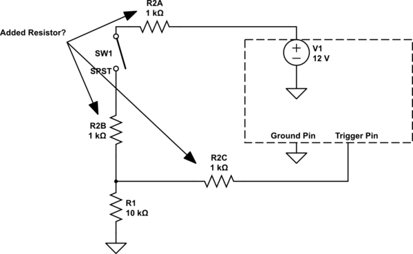
schematic

simulate this circuit – Schematic created using CircuitLab

The right boxed section is a connector where I showed the power pin (V1 @ 12V), trigger pin, and ground pin (chassis).

The left side is a (hopefully correctly drawn) pull-down resistor setup with SPST switch (SW1) and standard 10k resistor (R1).
Does this 10k resistor (R1) act as a current limiter in this circuit?
On the top of that, I added a 1k resistor (R2A OR R2B OR R2C) in series with the SPST switch (SW1) because i was wondering if it could be used as a "current limiting resistor".
I was also wondering if it matters where the resistor goes, whether its before or after the switch, shown by R2A & R2B & R2C.
What are the differences (if any) between positions R2B and R2C?

Also, I think this becomes a voltage divider right? where the voltage will be 10/11 * 12V at the trigger pin when the switch is closed?
If I didnt have resistor R2, then what voltage would the trigger pin see with the switch closed? 12V?

Can it "make sense" at all to put in this R2 resistor in this circuit? What uses can it have?

\$\endgroup\$
4
  • \$\begingroup\$ What is Trigger Pin? Is it a high impedance input, like an input pin on an IC or transistor? Or is it a low impedance input like the coil of a relay? \$\endgroup\$
    – bigjosh
    Commented Feb 22, 2015 at 22:21
  • \$\begingroup\$ Is V1 really a sine wave output, or is it a steady 12 volts DC? \$\endgroup\$
    – bigjosh
    Commented Feb 22, 2015 at 22:23
  • \$\begingroup\$ Trigger pin is an input pin... V1 is Switched 12 V DC... fixed. \$\endgroup\$
    – Zero
    Commented Feb 22, 2015 at 22:37
  • \$\begingroup\$ Is the Trigger pin an input to a microcontroller or other digital logic? If so, you may need a voltage divider to reduce the 12 V to a level acceptable to the microcontroller. \$\endgroup\$ Commented Feb 22, 2015 at 22:44

2 Answers 2

3
\$\begingroup\$

Yes, in your circuit, the resistors form a voltage divider when the switch is closed, assuming that the input impedance (how much current flows into it) of the Trigger pin is much higher than the value of the resistors.

When the switch is open, the 10K resistor R1 acts to keep the voltage on the Trigger Pin from floating. If, say, the Trigger Pin was to high impedance input (that is, it lets very little current flow though it, like the gate of a MOSFET), then without R1 it is possible that just stray electrical charges and fields could be enough to make the voltage on the Trigger Pin go high enough to trigger even though it is not connected to anything.

While you probably do not need the R2 resistor, it could in theory function to reduce the amount of current used when the switch is closed, or specifically to make sure the voltage reaching the Trigger Pin is always a little lower than (rather than equal to) V1 when the switch is closed.

Moving the resistor R2 before or after the switch could in theory also have effects. For example, if V1 is sensitive to voltage transients, then putting the resistor between the switch and V1 could help mitigate any static discharge that happens when someone physically touches the switch, at least compared to having the switch connected directly V1 and using resistor in position B2. Similarly, if you were worried about, say, a screwdriver falling into the switch and shorting the contacts to ground, then adding resistor R2 between the switch and V1 could limit the current in flowing in that case and prevent the short from blowing out the power supply or the connecting wires.

None of these theoretical effects probably matter in your circuit, but in practice they can be a real consideration. Check out this question (of mine!) where the location of the resistor is important for similar reasons...

What is the purpose of adding a 300 ohm to 500 ohm resistor on the Neopixel data line?

\$\endgroup\$
10
  • \$\begingroup\$ Can R2 really be used to reduce the current when the switch is closed?? How will the current "behave" with R2 and without? Will the current limiting effects be dwarfed by R1 or does it actually make some difference for the current going to the trigger?? \$\endgroup\$
    – Zero
    Commented Feb 22, 2015 at 21:39
  • \$\begingroup\$ So in essence, are you saying that it MIGHT/COULD be helpful to have the resistor between the switch and V1 while there are probably no benefits to having the resistor in R2B position?? \$\endgroup\$
    – Zero
    Commented Feb 22, 2015 at 21:40
  • \$\begingroup\$ @Zero I = V/R. You're voltage is fixed, but you have two sitations where your total resistance is 10k, or its 11k. As resistance increases, current decreases. \$\endgroup\$
    – efox29
    Commented Feb 22, 2015 at 21:40
  • \$\begingroup\$ Having R2 in either position will really reduce the current that flows when the switch is closed. It is increasing the resistance that the voltage from V1 has to flow though by 1K ohms, so there will be less current. In this example it does not reduce it by that much, but in some cases (like a battery powered circuit I recently worked on), putting a big resistor (50K) in series with a button reduced the ammount of power consumed when the button was pushed by an order of magnatude. \$\endgroup\$
    – bigjosh
    Commented Feb 22, 2015 at 21:43
  • \$\begingroup\$ Having R2 in position B actually could make sense if, say, the trigger input was very sensitive to transients but V1 was not. This way, any static discharge that happened from a person physically touching the switch would be reduced by R2 before hitting the Trigger Pin. \$\endgroup\$
    – bigjosh
    Commented Feb 22, 2015 at 21:44
0
\$\begingroup\$

Also, I think this becomes a voltage divider right? where the voltage will be 10/11 * 12V at the trigger pin when the switch is closed?

It does become a voltage divider, however it divides by a ratio of 10/12 ( you forgot the other 1k resistor).

If I didnt have resistor R2, then what voltage would the trigger pin see with the switch closed? 12V?

The voltage would be whatever V1 is at that instant. If its a sinusoid, the voltage on your trigger would be the same. If its DC, then you'll see 12V.

Can it "make sense" at all to put in this R2 resistor in this circuit? What uses can it have?

I don't see a need for R2 unless you need to scale the voltage down. It also doesn't matter if you have 2 resistors, (like R2A and R2B) or just one resistor (R2). It also does not matter whether its before the switch or after the switch. They all will do the same thing - scale the voltage down.

If all you are trying to do is set your trigger off with 12V when the switch closes, then you dont need R2 (A and B). The 10K pulldown is all you need.

\$\endgroup\$
1
  • \$\begingroup\$ the 2 1k resistors are an EITHER OR thing. I am now also asking if it matters where the resistor goes, before or after the switch so I added both locations. Thanks! \$\endgroup\$
    – Zero
    Commented Feb 22, 2015 at 21:33

Your Answer

By clicking “Post Your Answer”, you agree to our terms of service and acknowledge you have read our privacy policy.

Not the answer you're looking for? Browse other questions tagged or ask your own question.